


Turbine Conversion Of Freewing 90mm Eurofighter
 04-25-2023, 03:39 PM
#1

Thread Starter
My Feedback: (20)
I've had two Eurosport jets and really enjoyed flying them both. When I saw the Freewing 90mm Eurofighter I jumped on the pre-order. I expect this jet to fly very well and based on videos I've see so far it looks like it will.
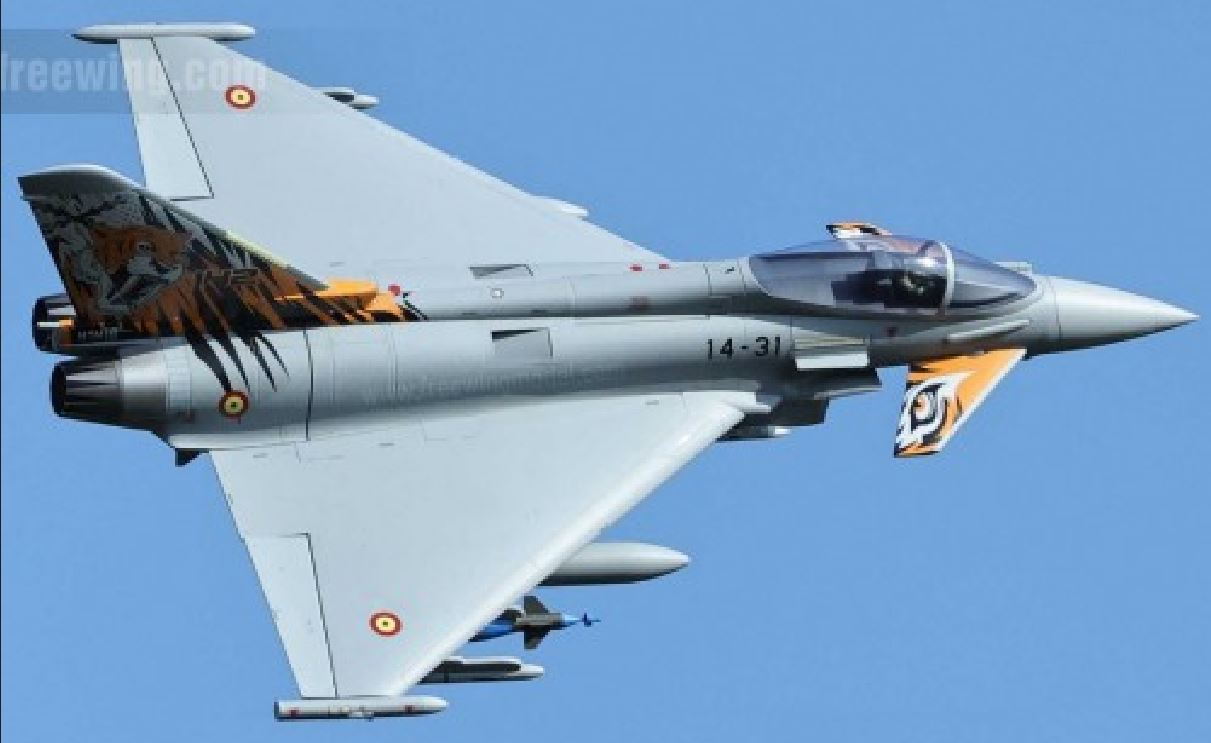
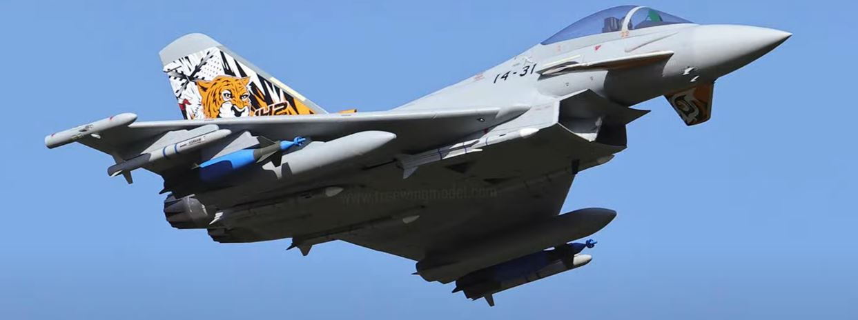

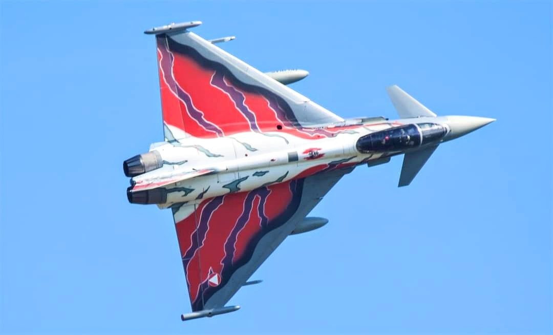
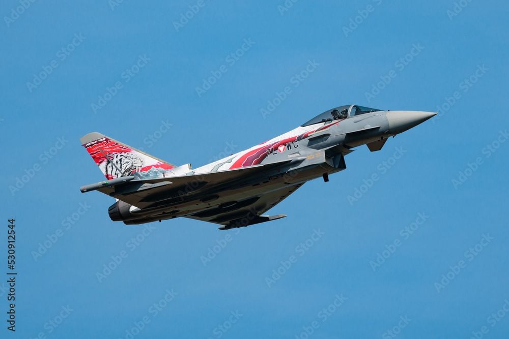
This is the Austrian full scale demo scheme that I plan to apply after test flights and initial adjustments
This thread will not be a step by step but a photo overview of the process. Hopefully it will inspire someone to see better ways to do it and share their ideas. I'll be using an X-45 but a K-45 or similar will work.
Last edited by Viper1GJ; 04-25-2023 at 04:16 PM.
 04-25-2023, 03:58 PM
#2
Thread Starter
My Feedback: (20)
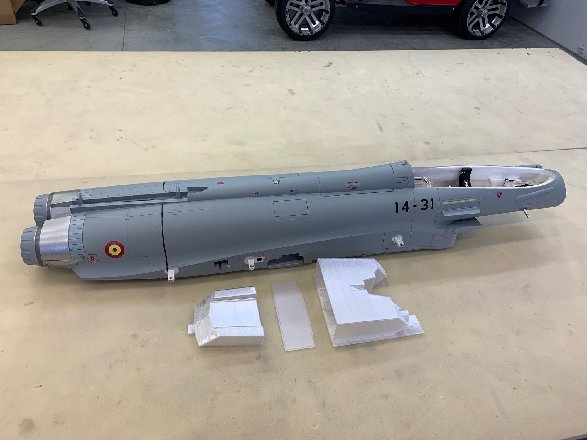
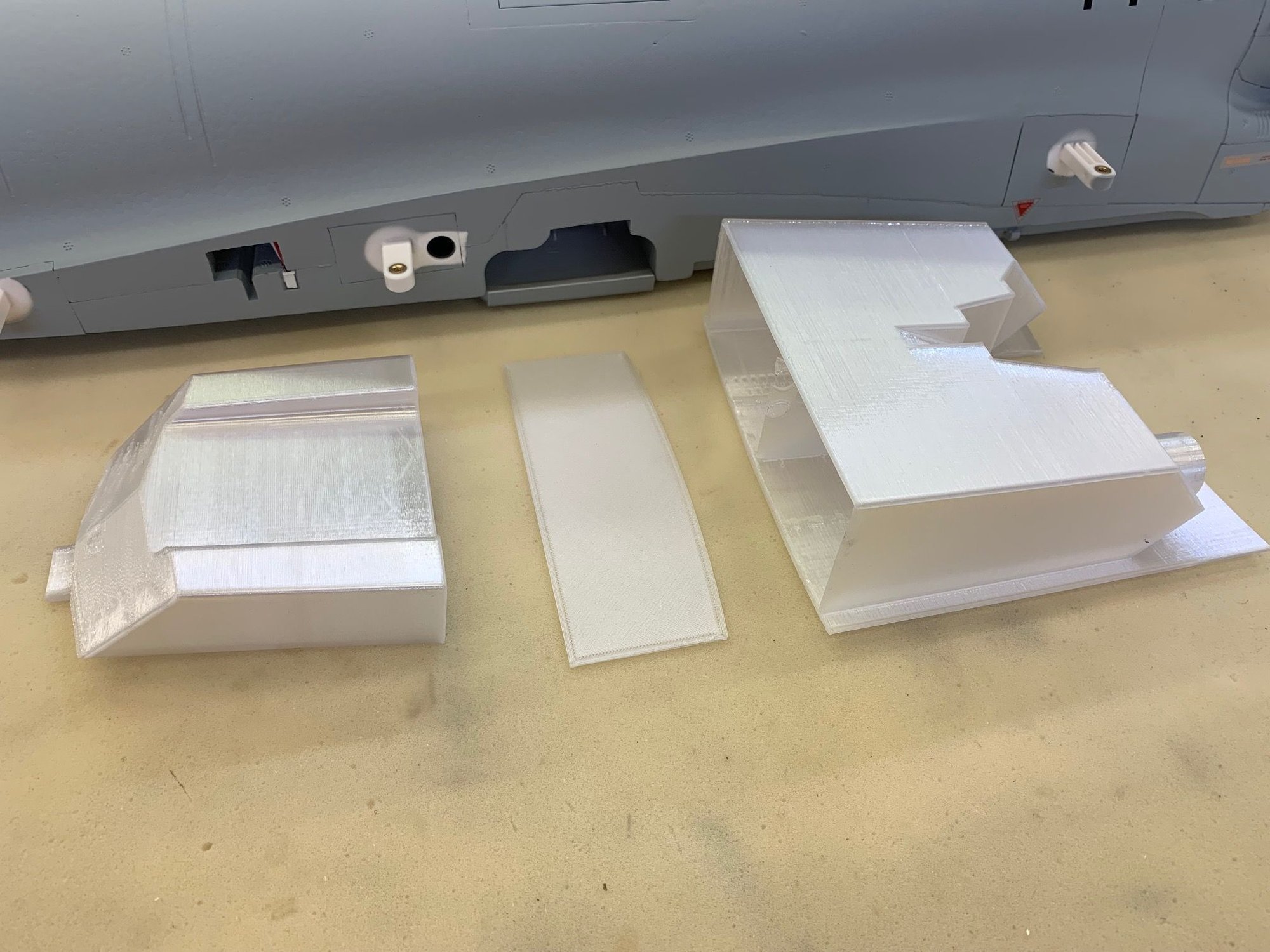
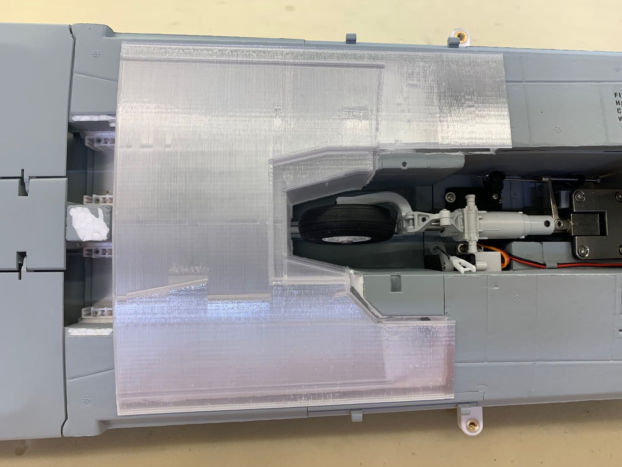
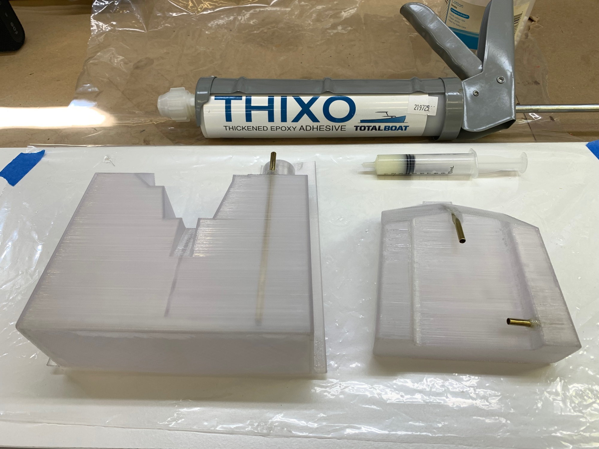
The two main issues for me with foamy EDF conversions are fuel tank of large enough size near the CG to get 7-8 minute flights and mounting the turbine and pipe. For the Eurofighter the tank is a challenge. I again ask my talented friend Keith to help and had my pre-order shipped to his house. He was able to design, 3D print, and fit a pair of tanks into the fuse. The front tank is about 30 oz and the aft aux tank is about 10 oz. This will be plenty for 7-8 min flights.
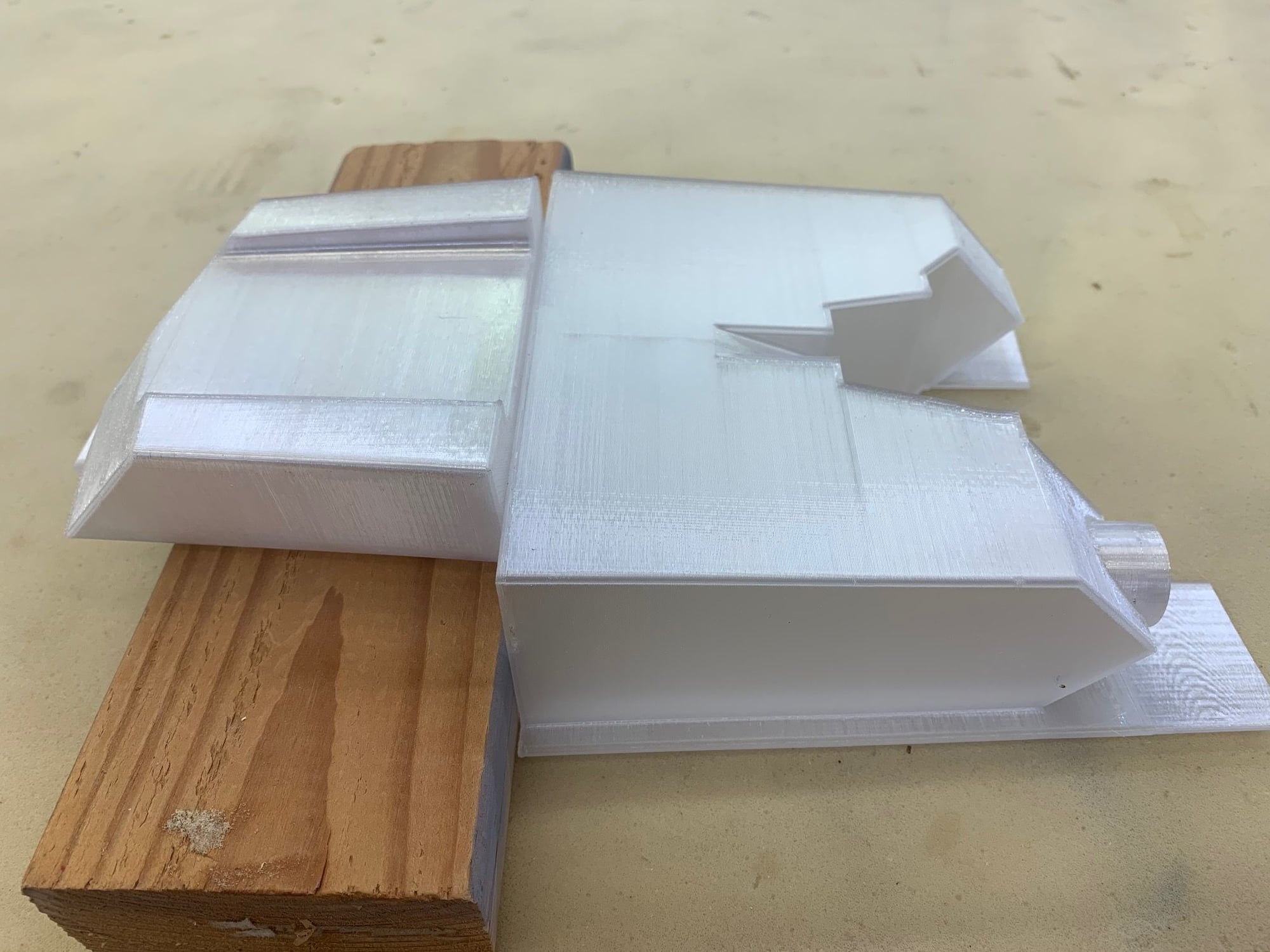
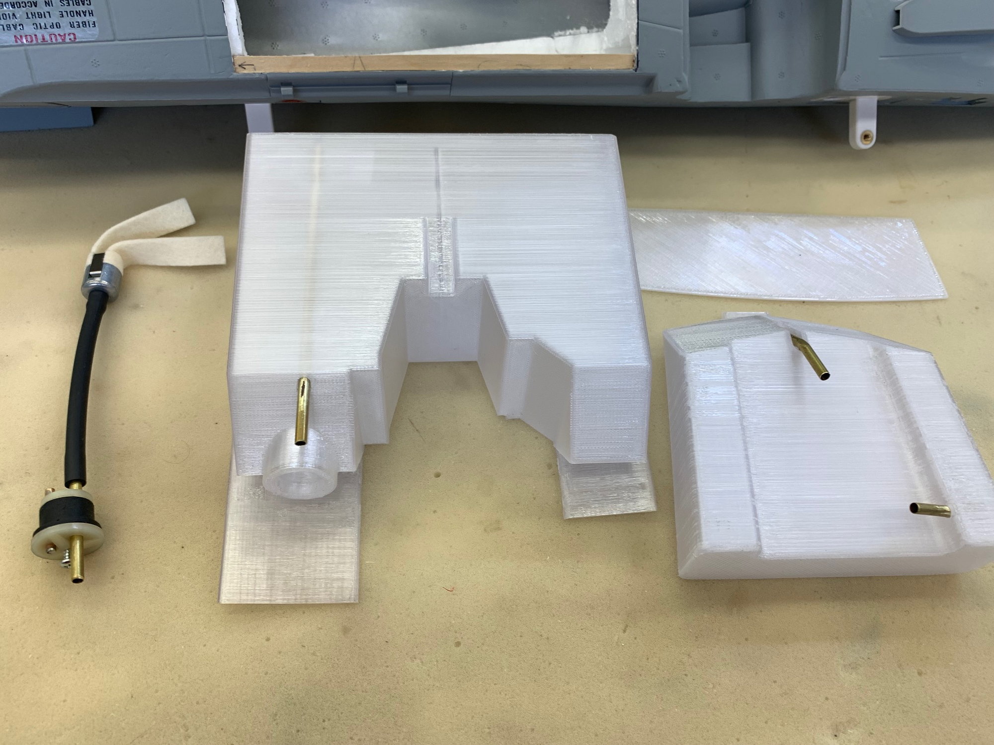
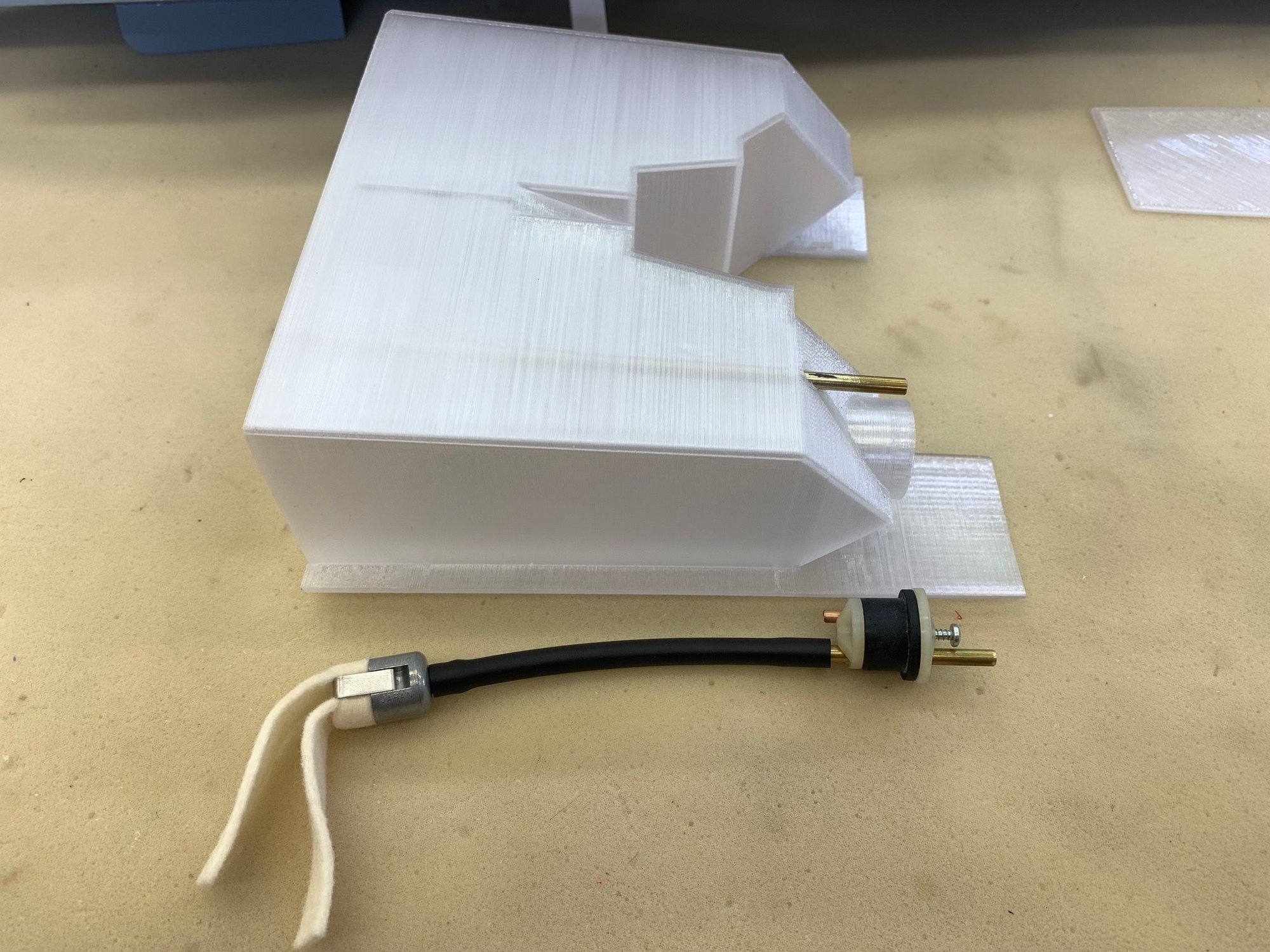
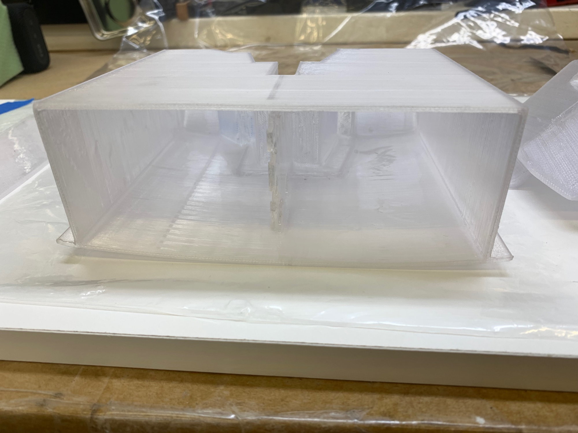
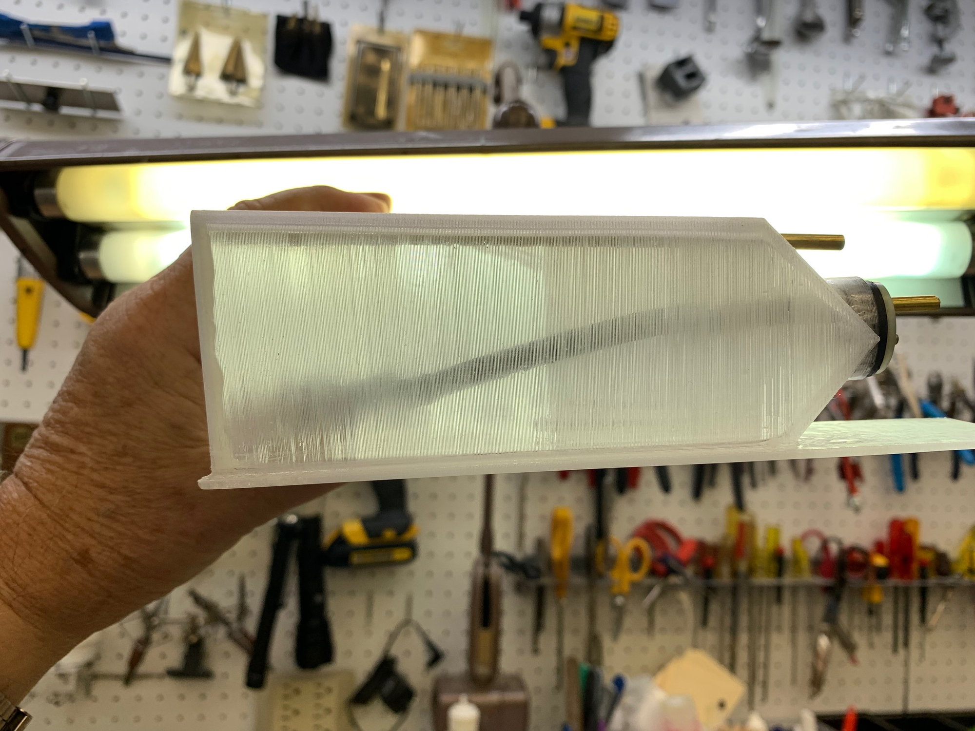
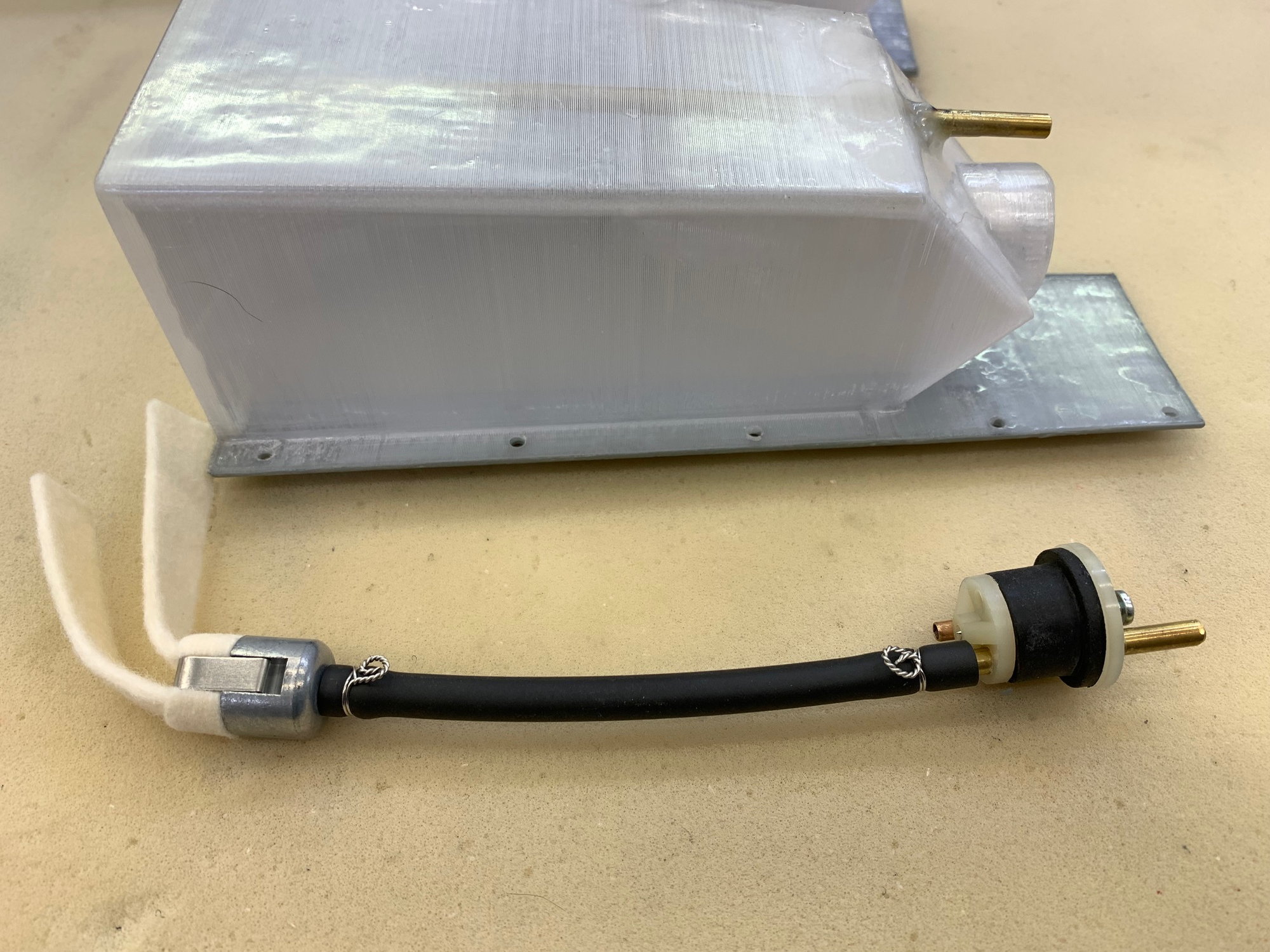
Tanks are printed with clear PETG filament. This shows the approximate orientation of tanks when installed. The aft tank will have a fixed brass tube pick up to feed the front tank and the front tank will have a rubber stopper mounted standard winged felt clunk. Both tanks have been slightly revised since these were printed with some slight changes but the concept is the same.
The front tank has a back plate that has to be epoxied in. Both tanks have to have epoxy sealing inside and out to plug any pin holes from PETG printing.
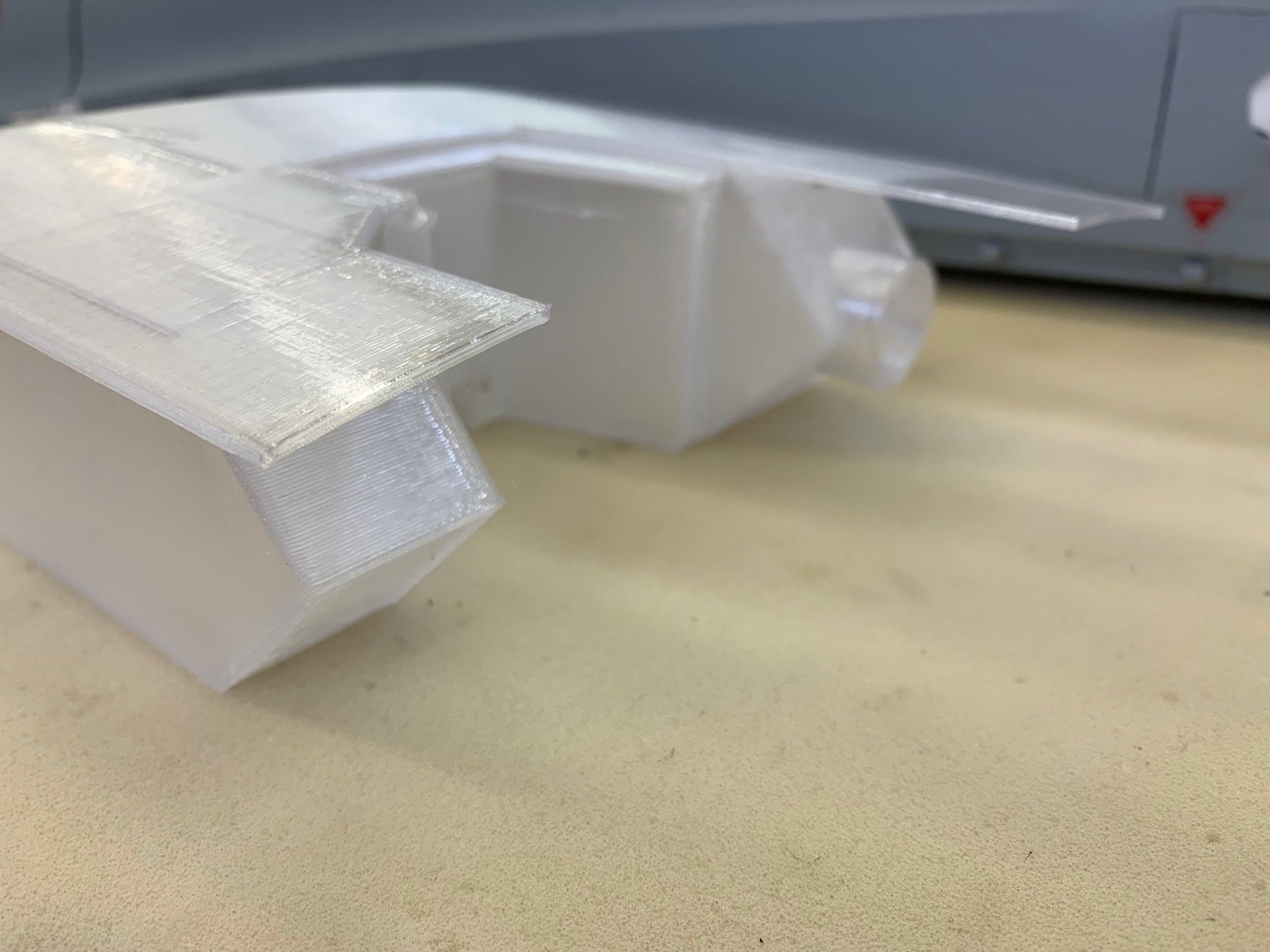
The tank is inverted here showing the stopper hole. The bottom of the tank (on top in this photo) is the bottom skin of the aircraft behind the nose gear well.
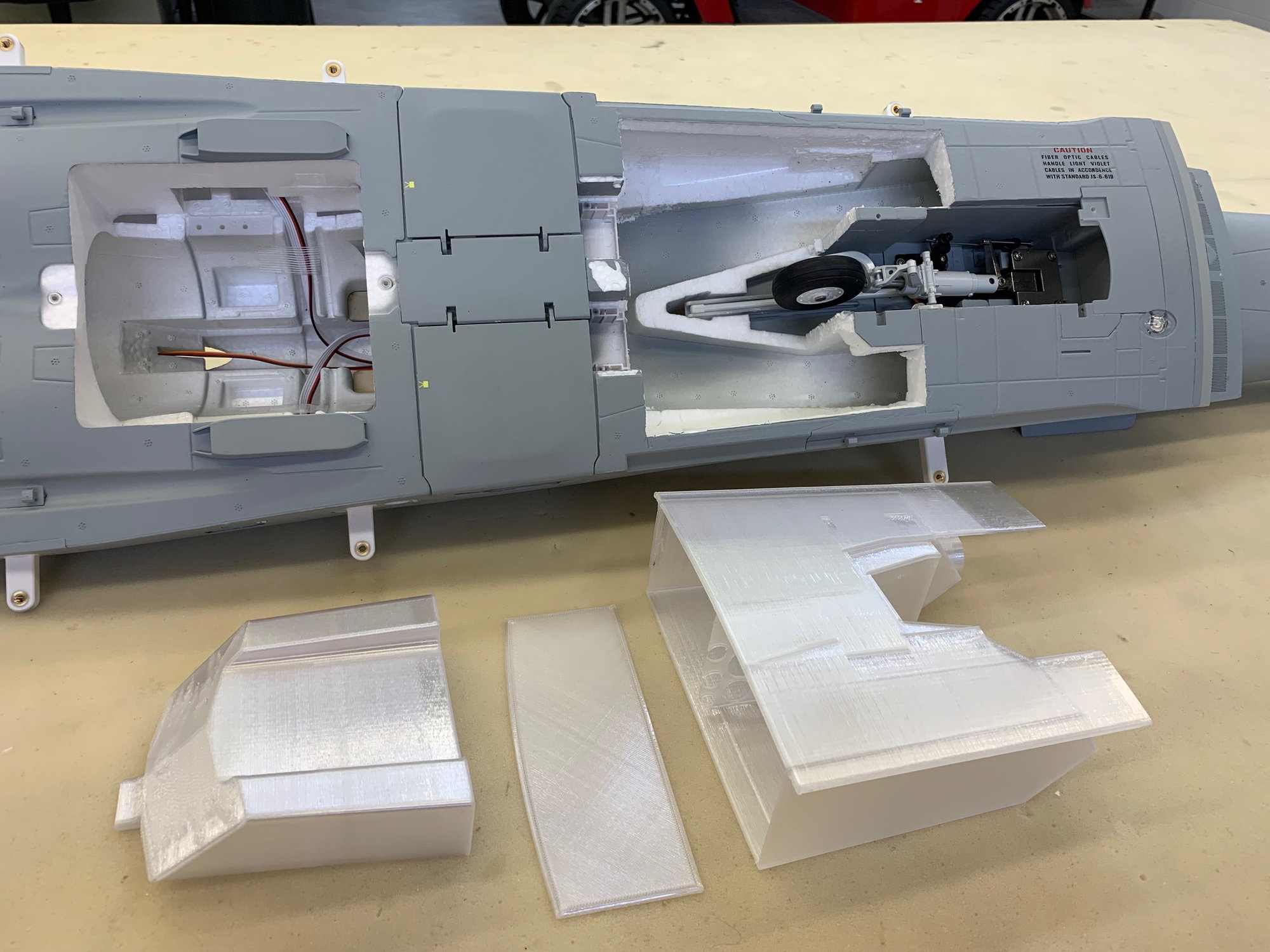
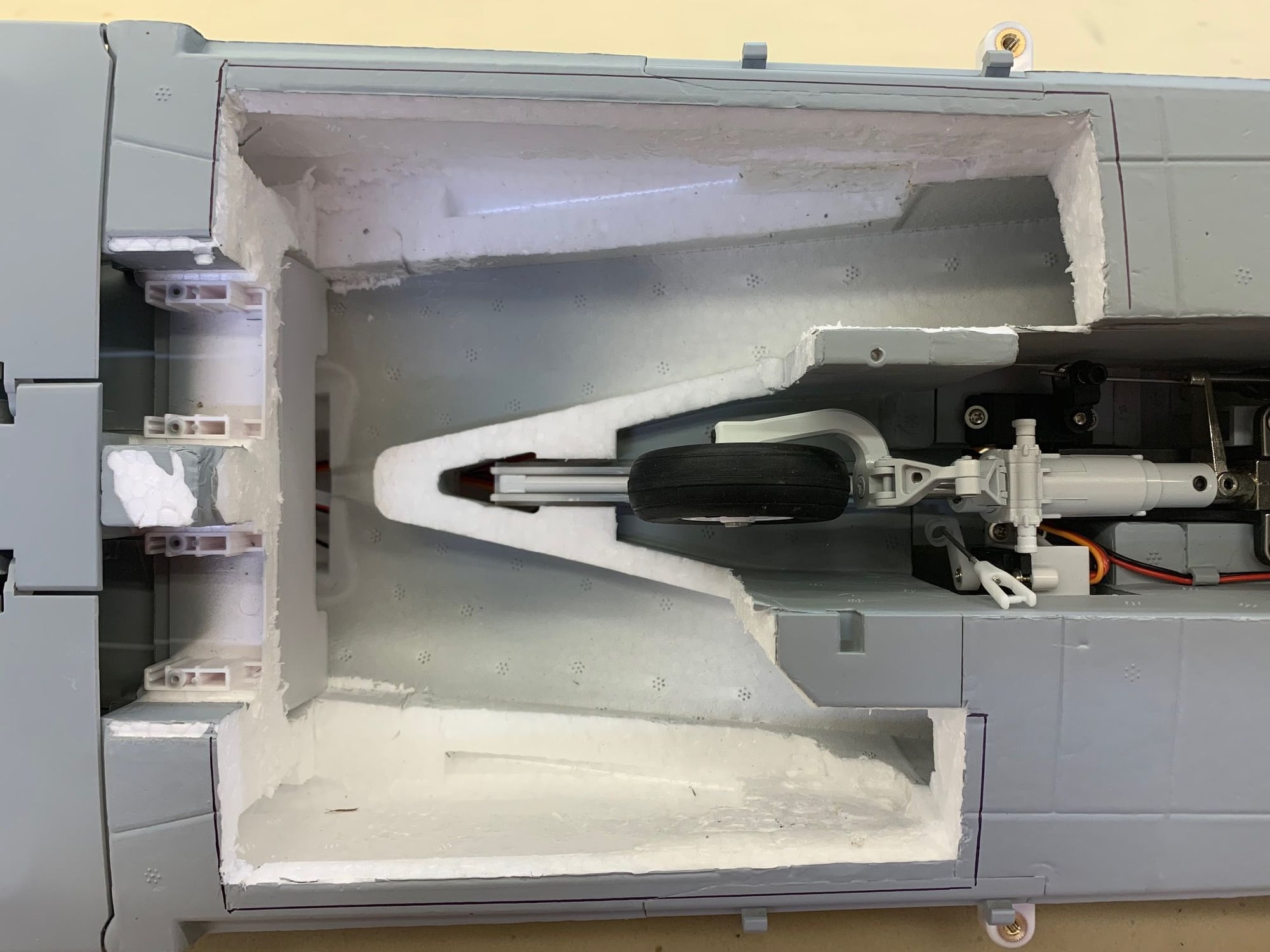
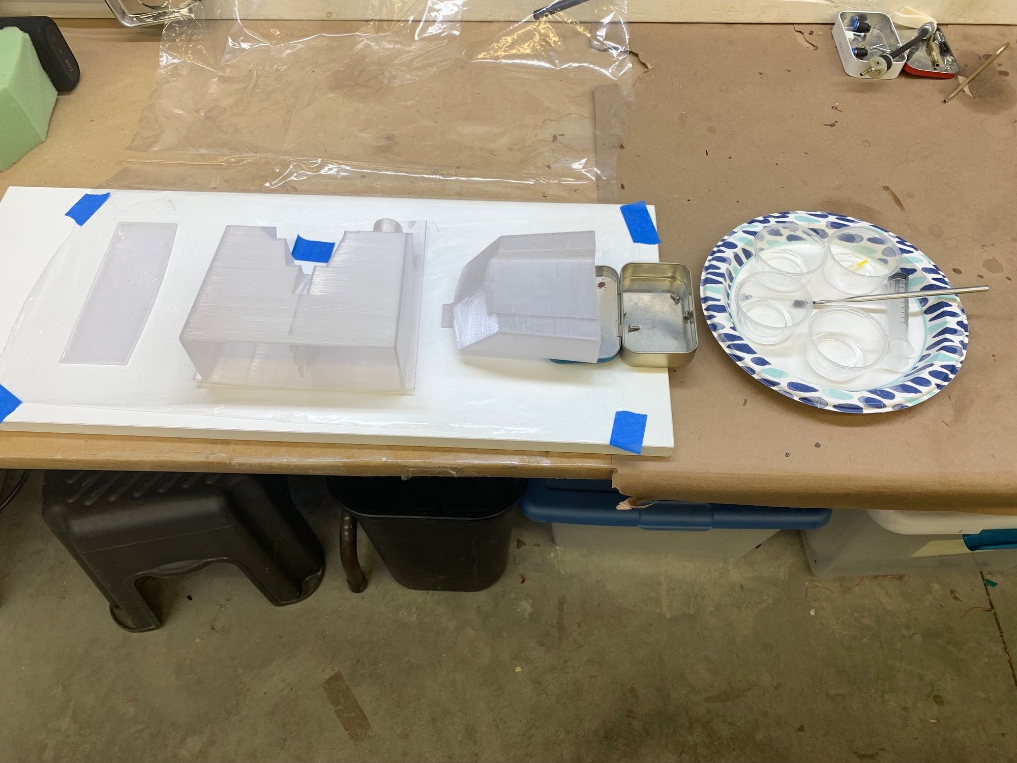
This is the foam cut out Keith made for the tanks and this is how I got the aircraft from him.
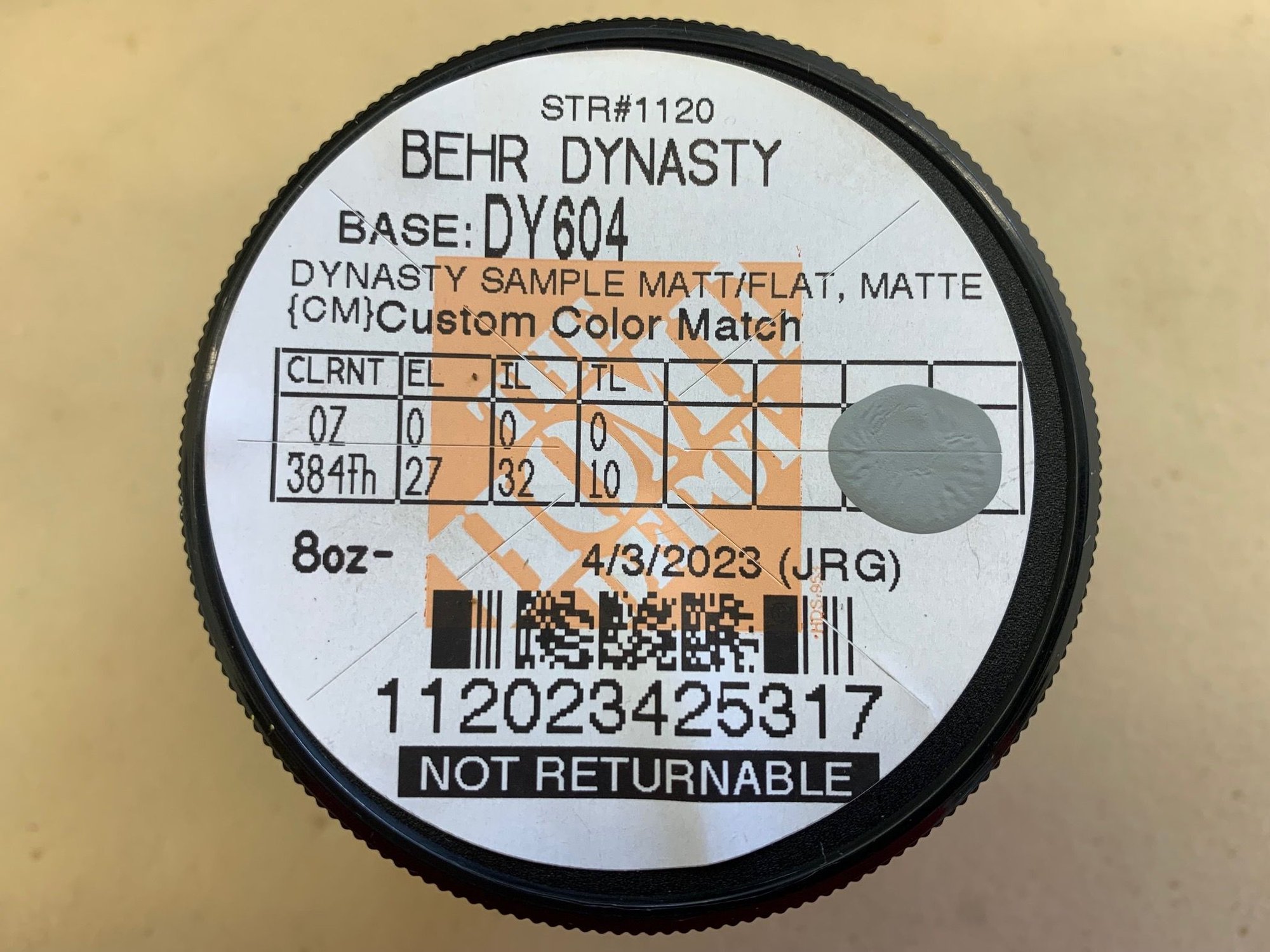
One of the first thing I do with a foamy conversion is get some matching touch up paint. Here is what Home Depot mixed up from a scan of the canard paint. Its pretty close.
Last edited by Viper1GJ; 04-25-2023 at 04:02 PM.
04-25-2023, 04:25 PM
#3
Thread Starter
My Feedback: (20)
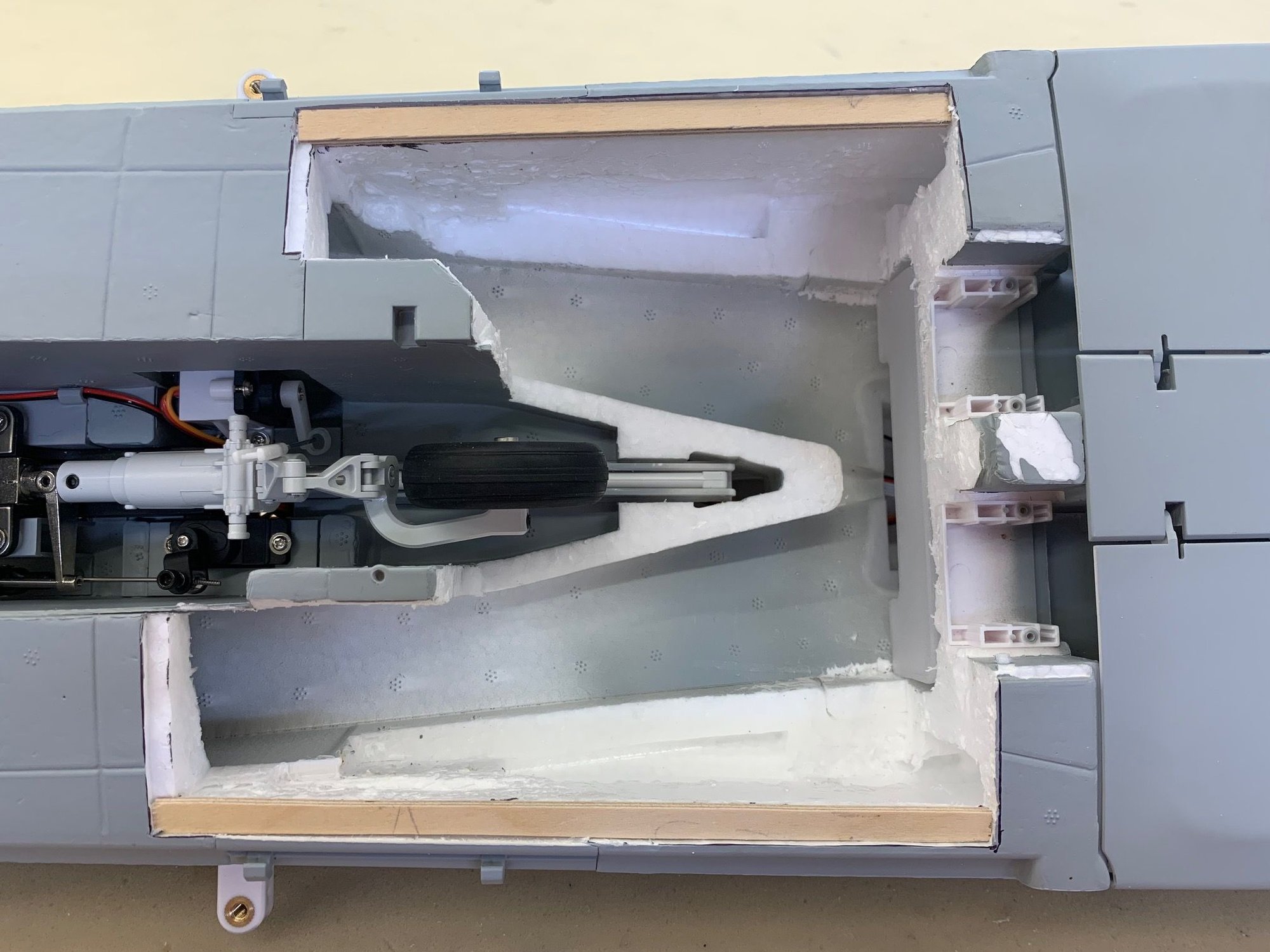
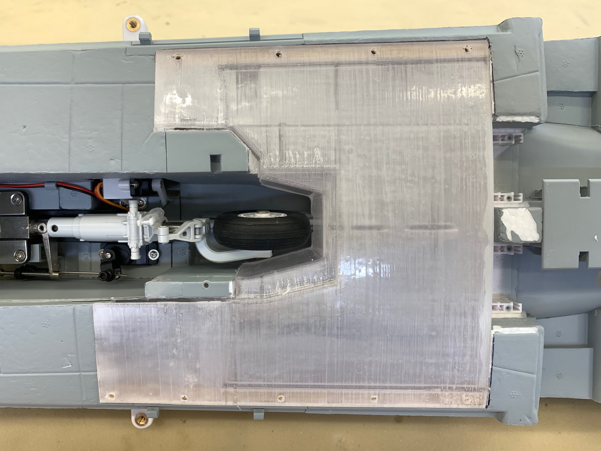
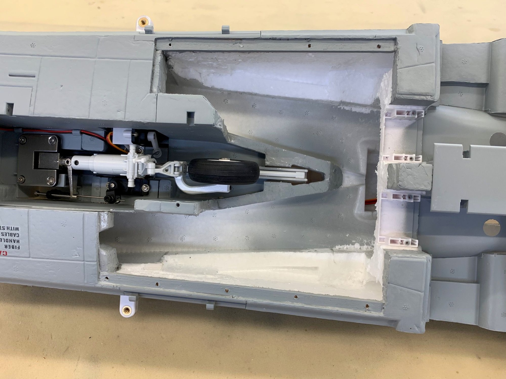
The aft tank slides into the air duct from front to back
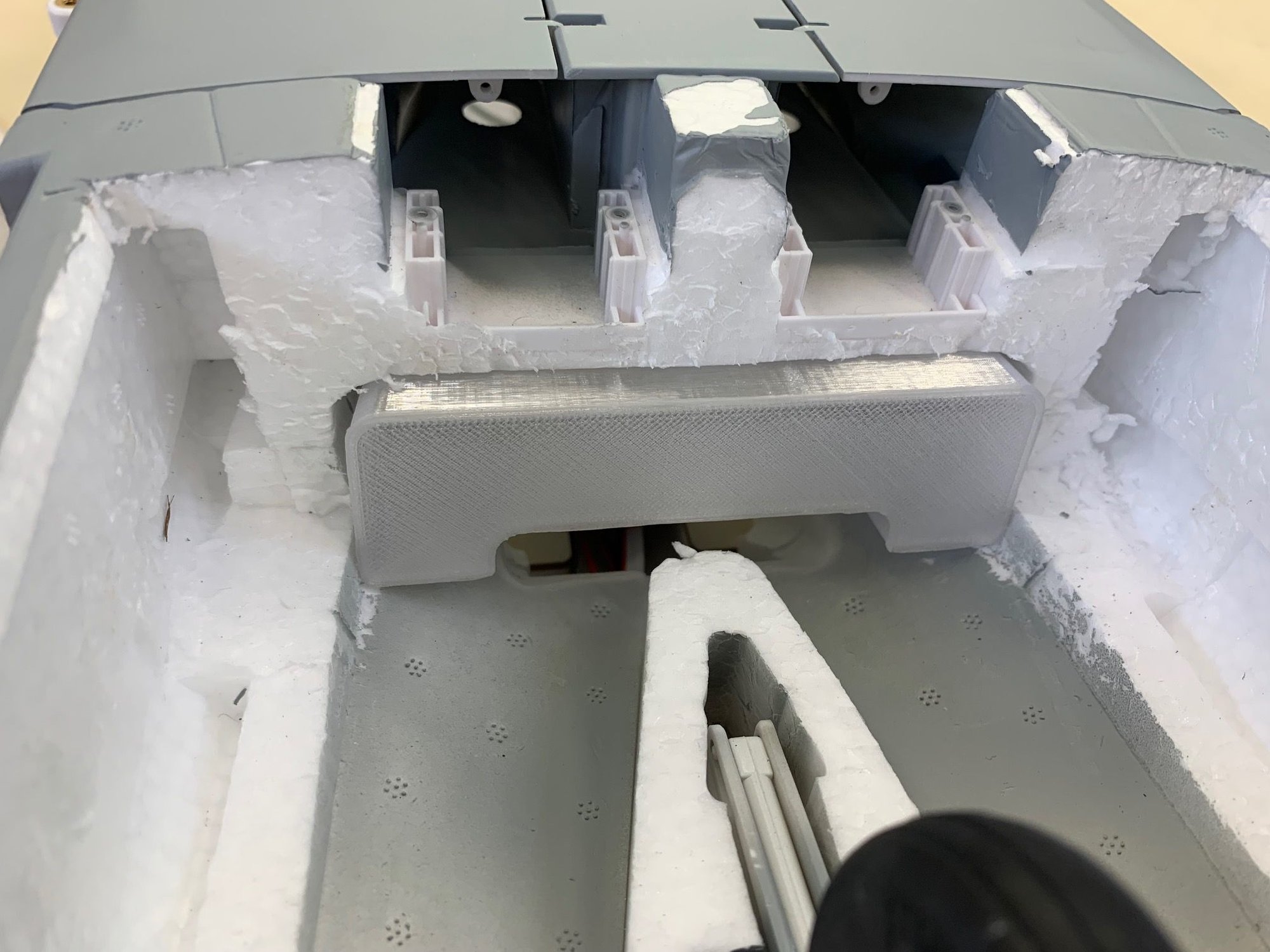
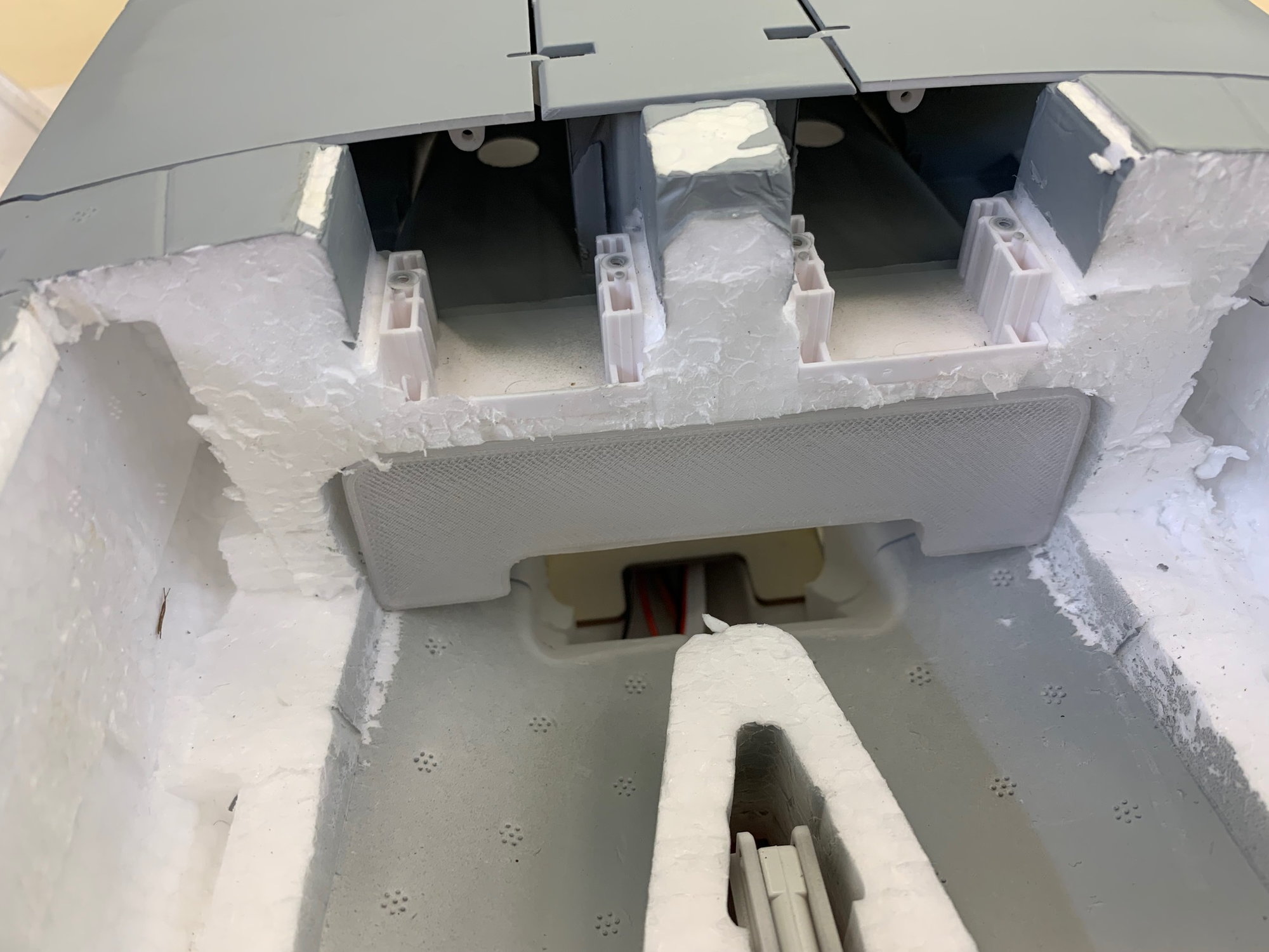
When in place the tank is flush with the main gear door servo mounts
The tab on the back of the tank clips over the main wing spar tube and holds the tank in place. It can't move and requires no fasteners. Genius design by Keith.


The following 2 users liked this post by Viper1GJ:
CNeuhausel (05-05-2023),
jcterrettaz (04-29-2023)
04-25-2023, 04:39 PM
#5
Thread Starter
My Feedback: (20)
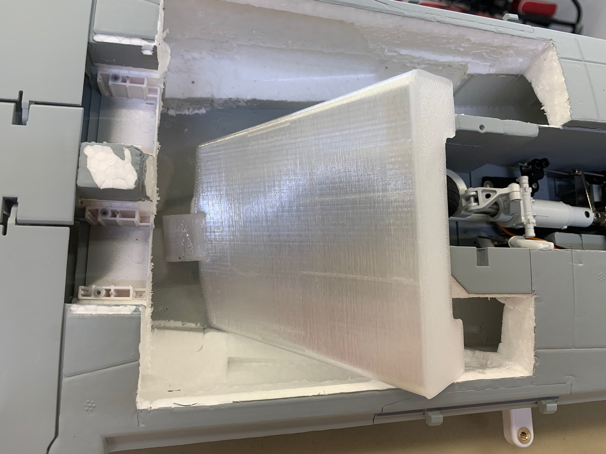
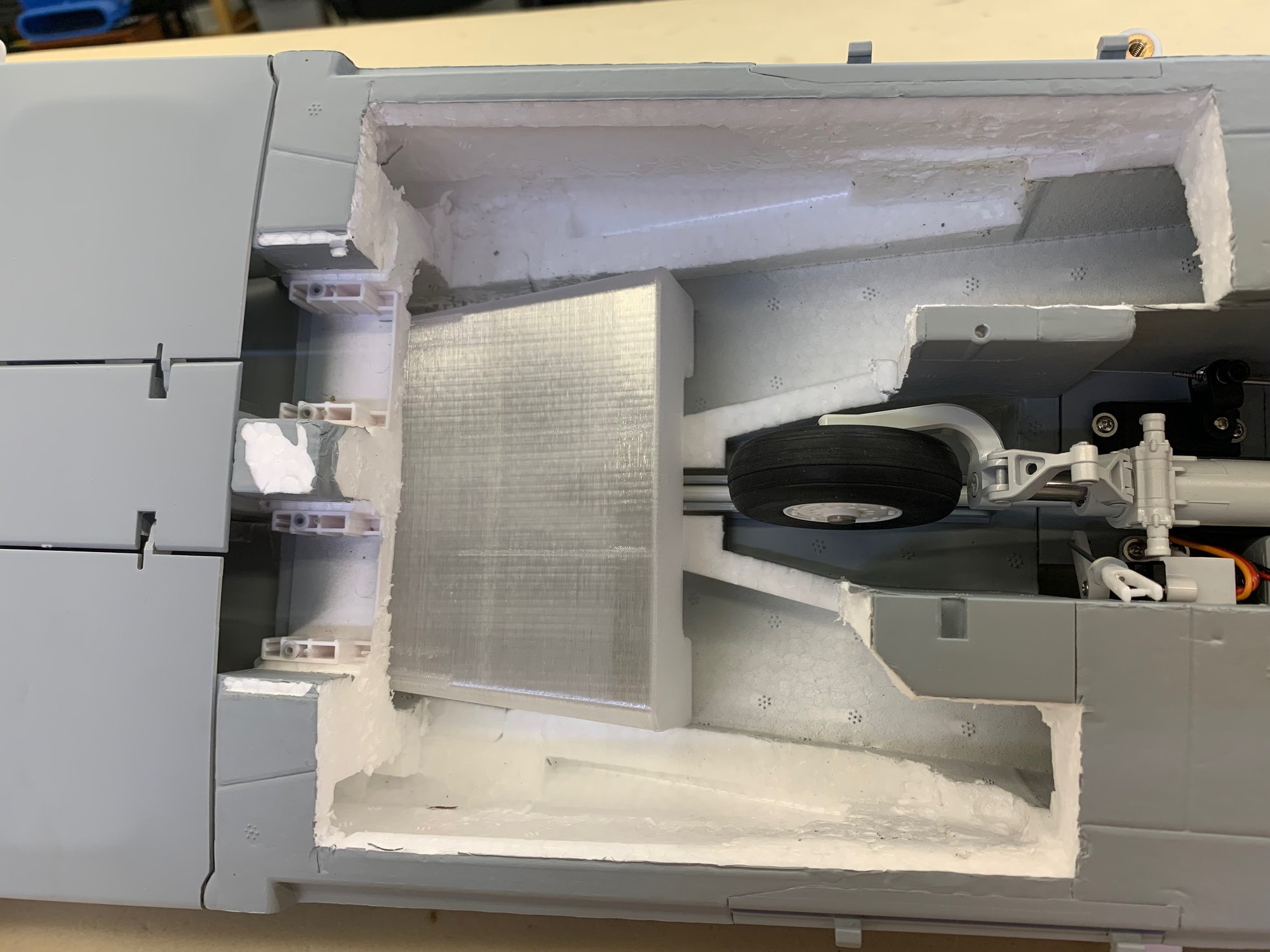
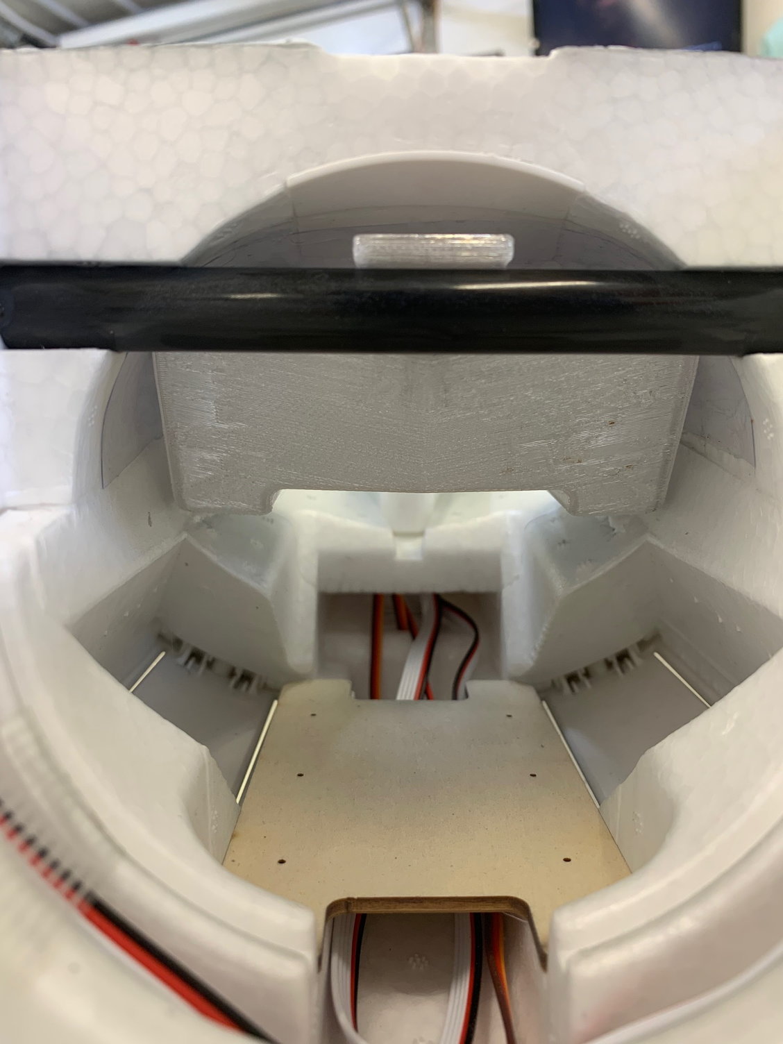
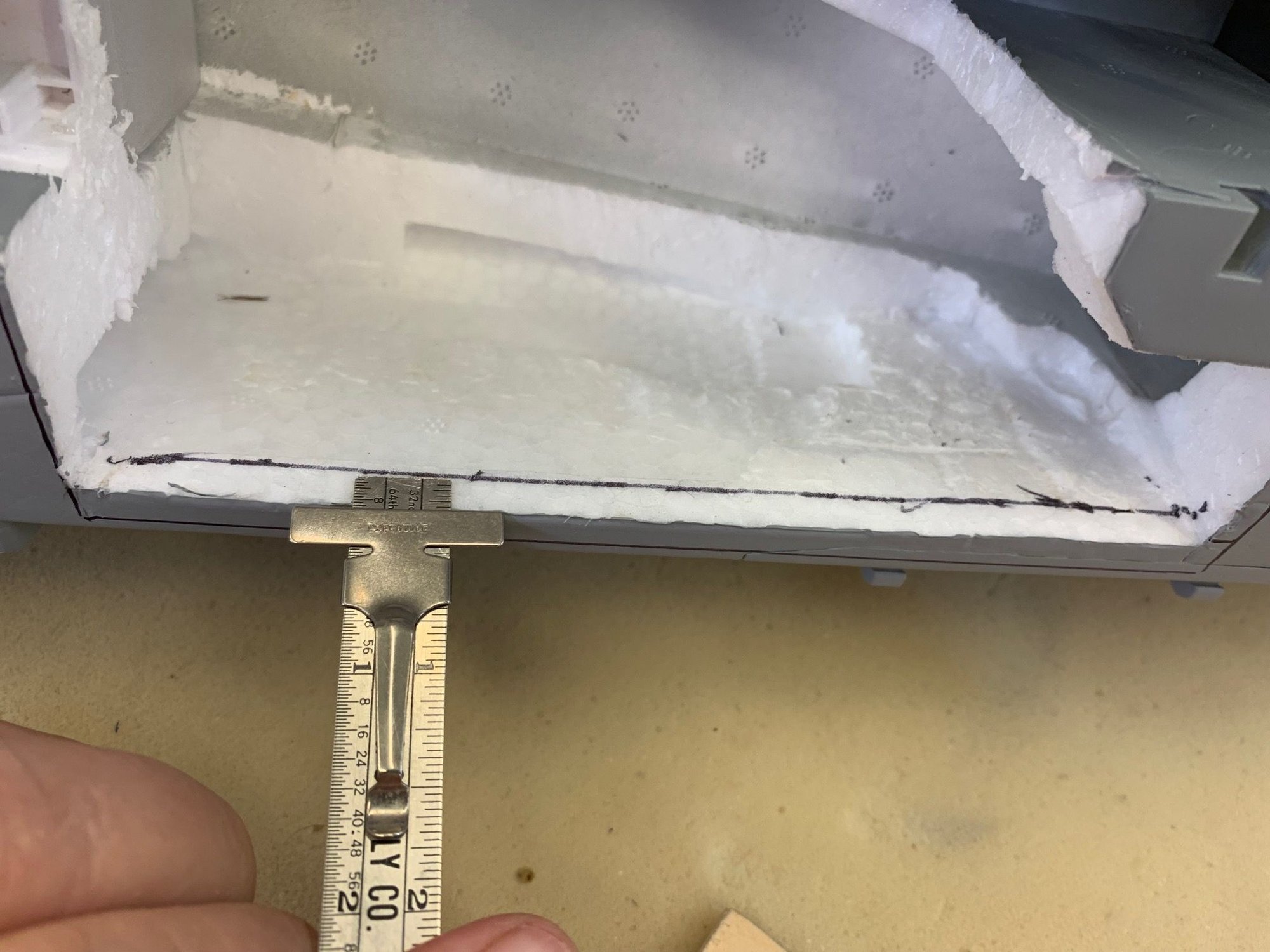
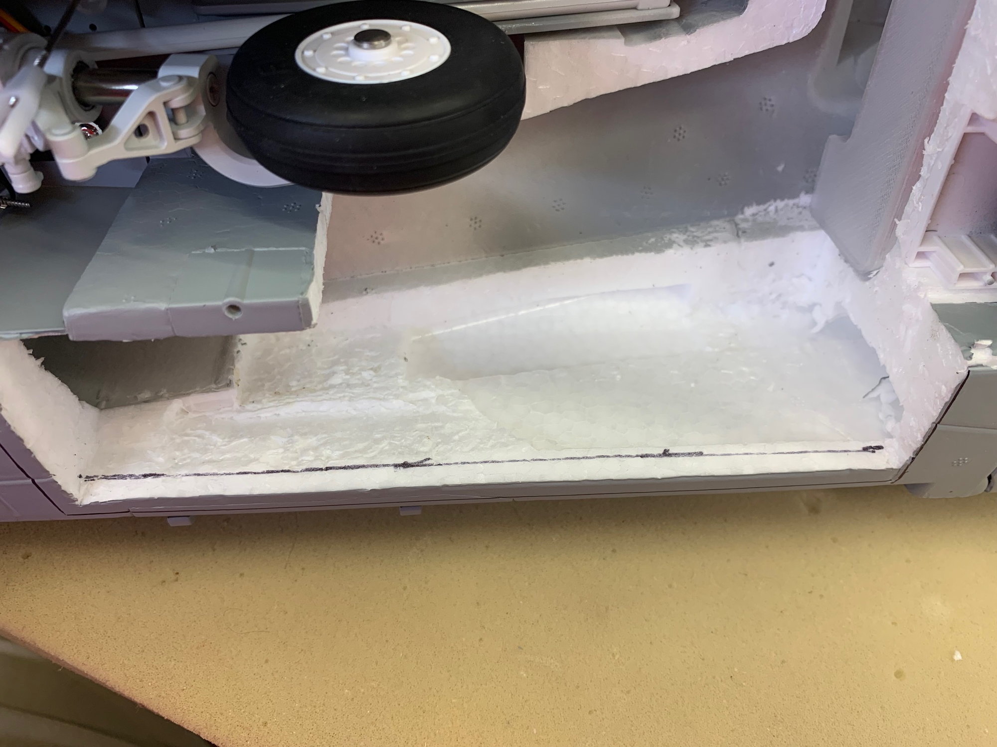
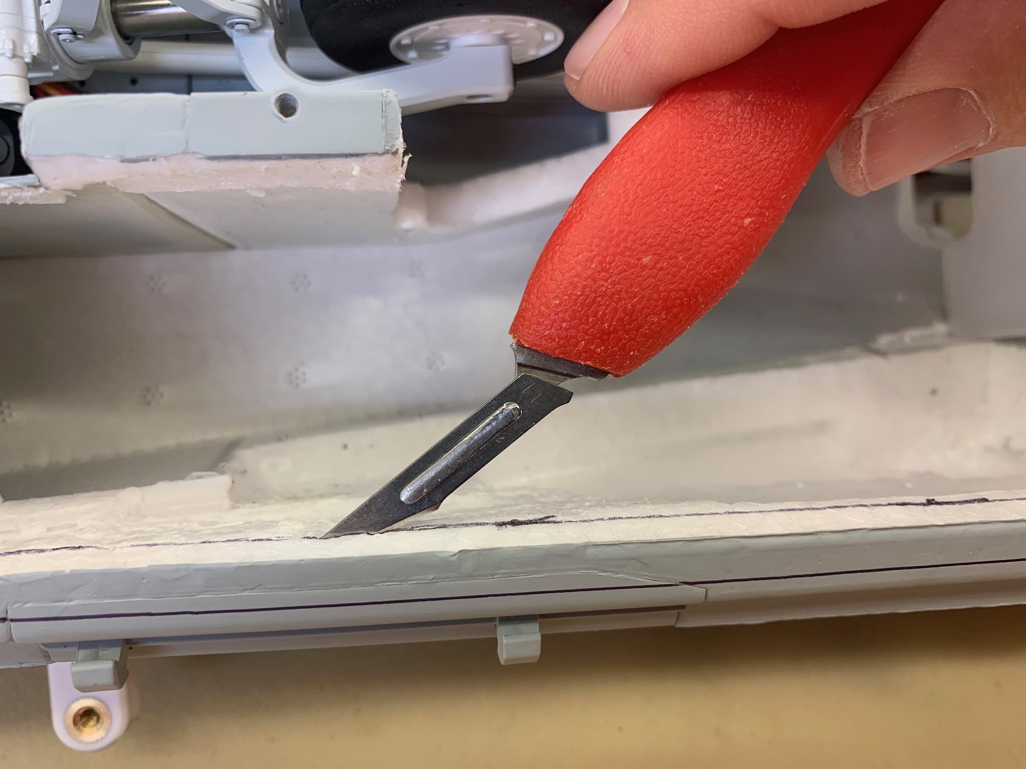
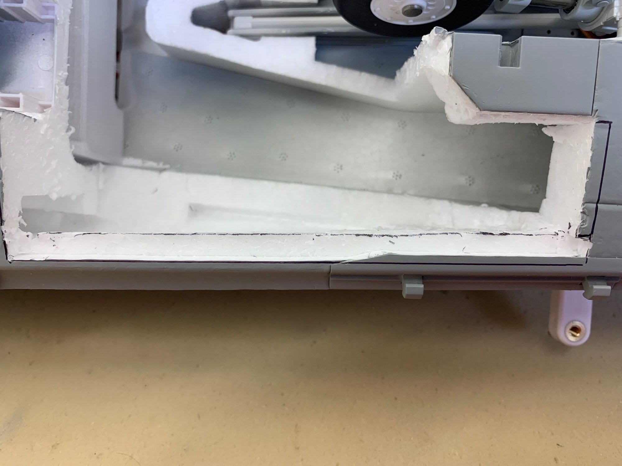
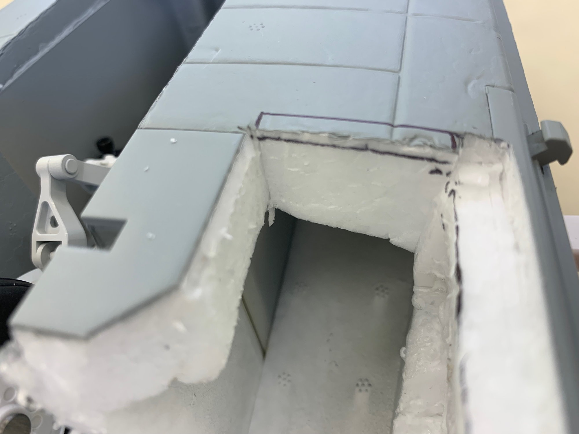
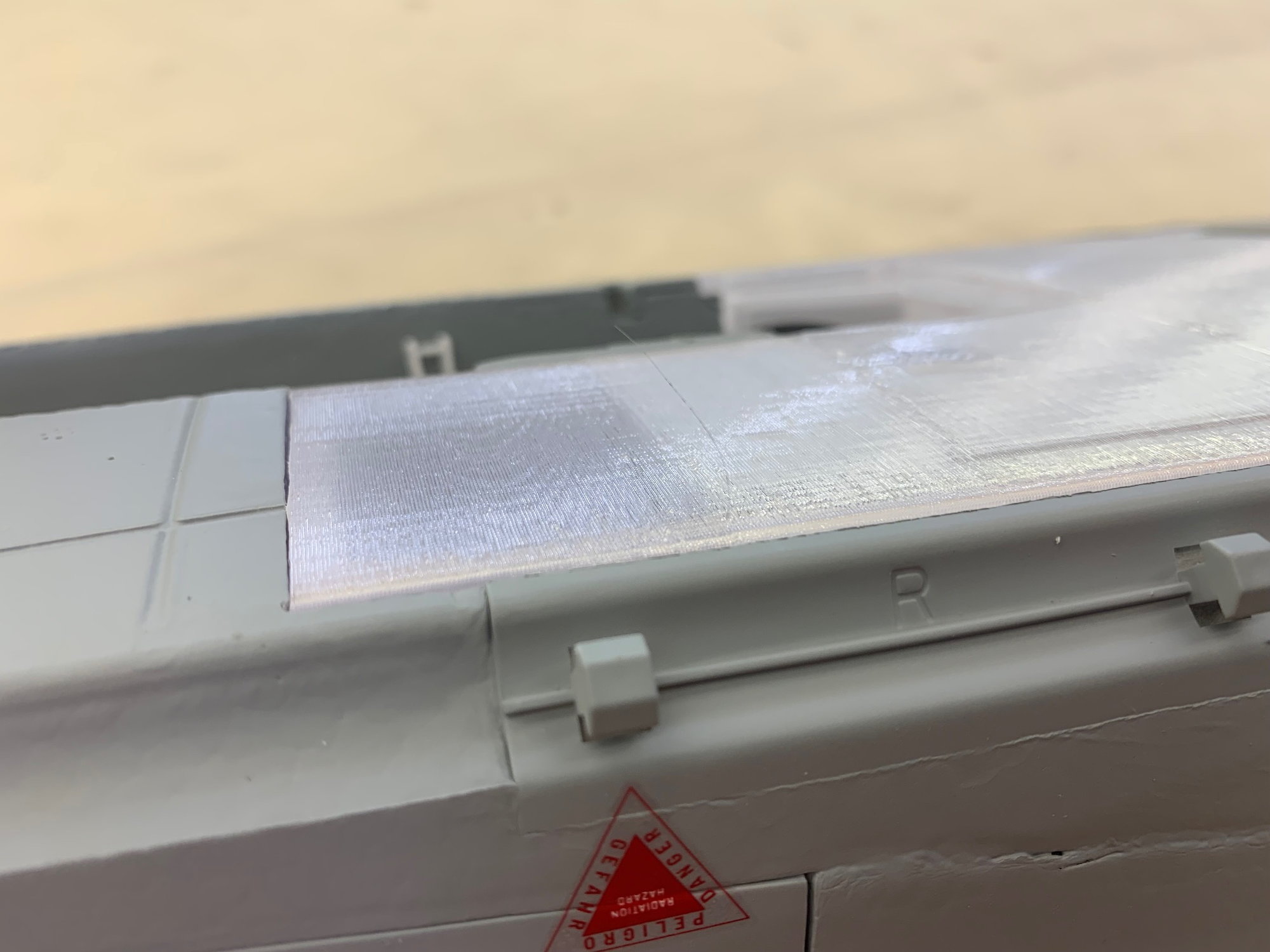
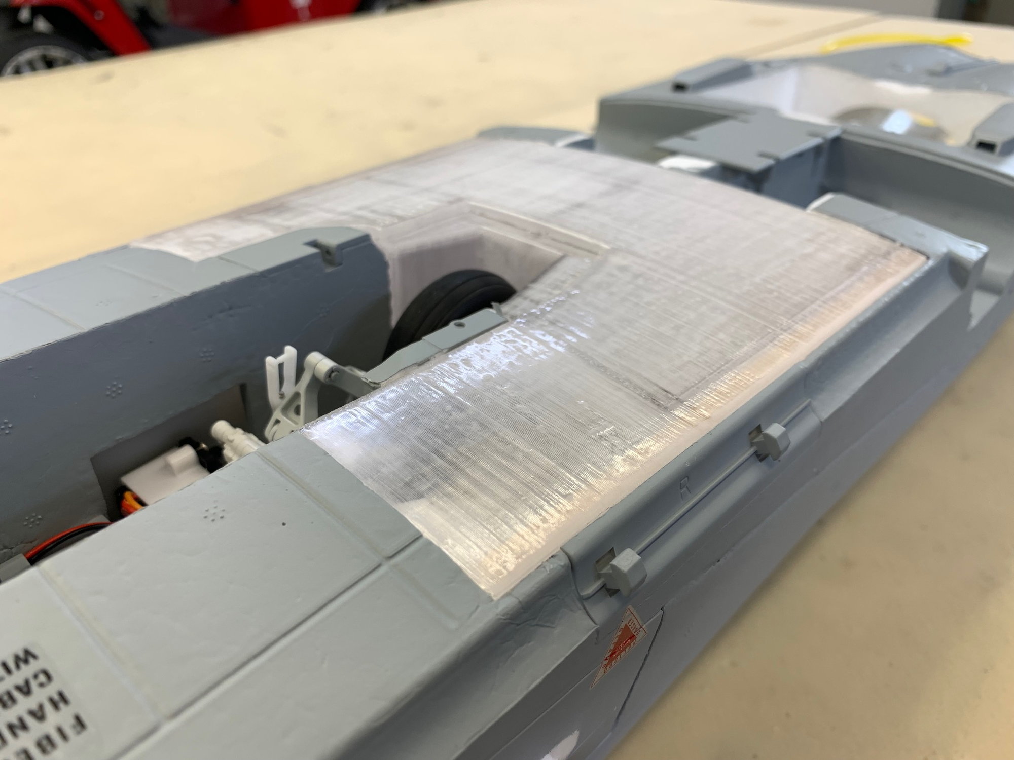
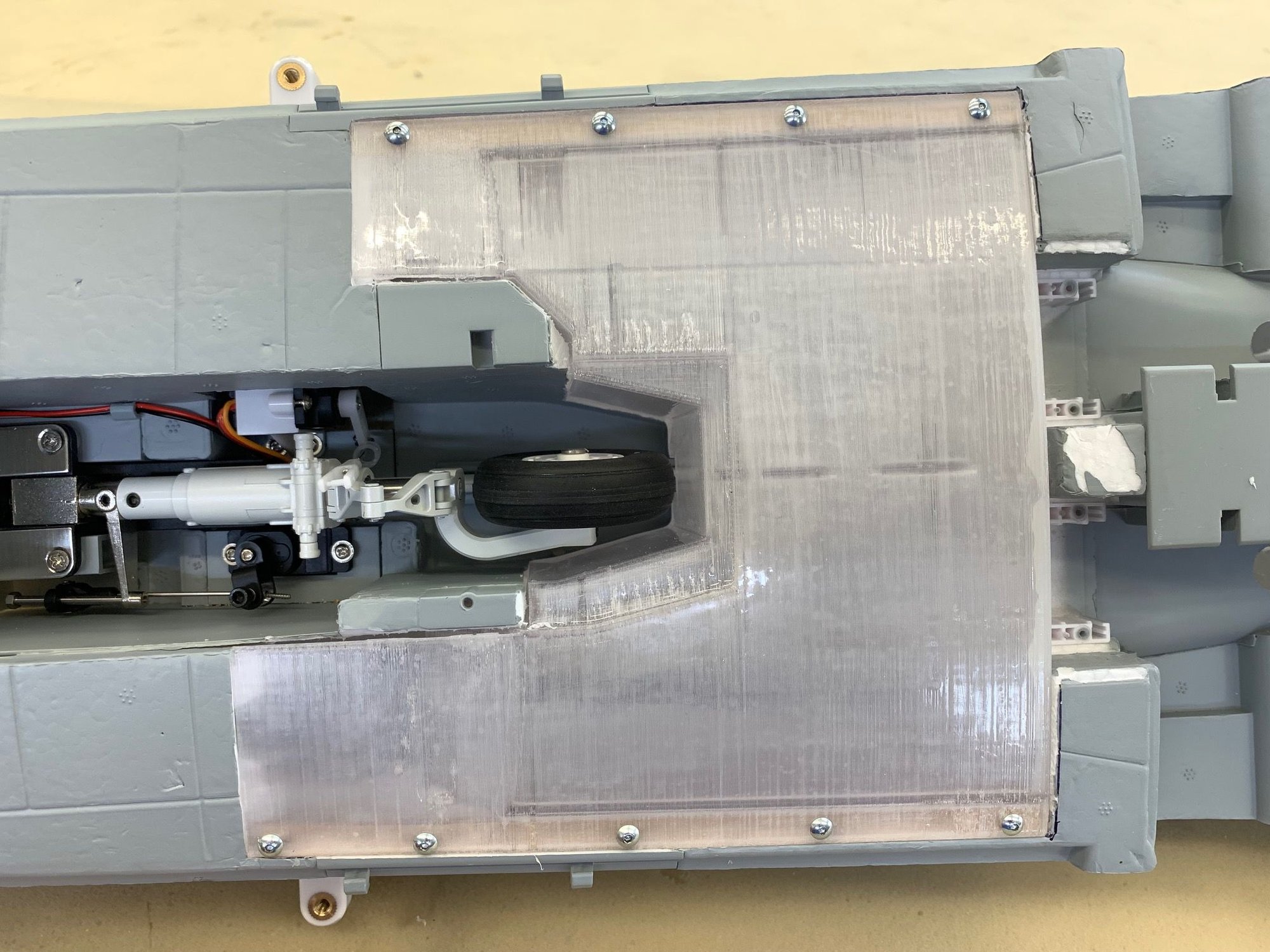
The main tank is held in place with screws on each side into wood rails embedded into the foam. I made relief cuts for the rails and tank to fit the tank flush with bottom skin

04-25-2023, 04:49 PM
#6
Thread Starter
My Feedback: (20)

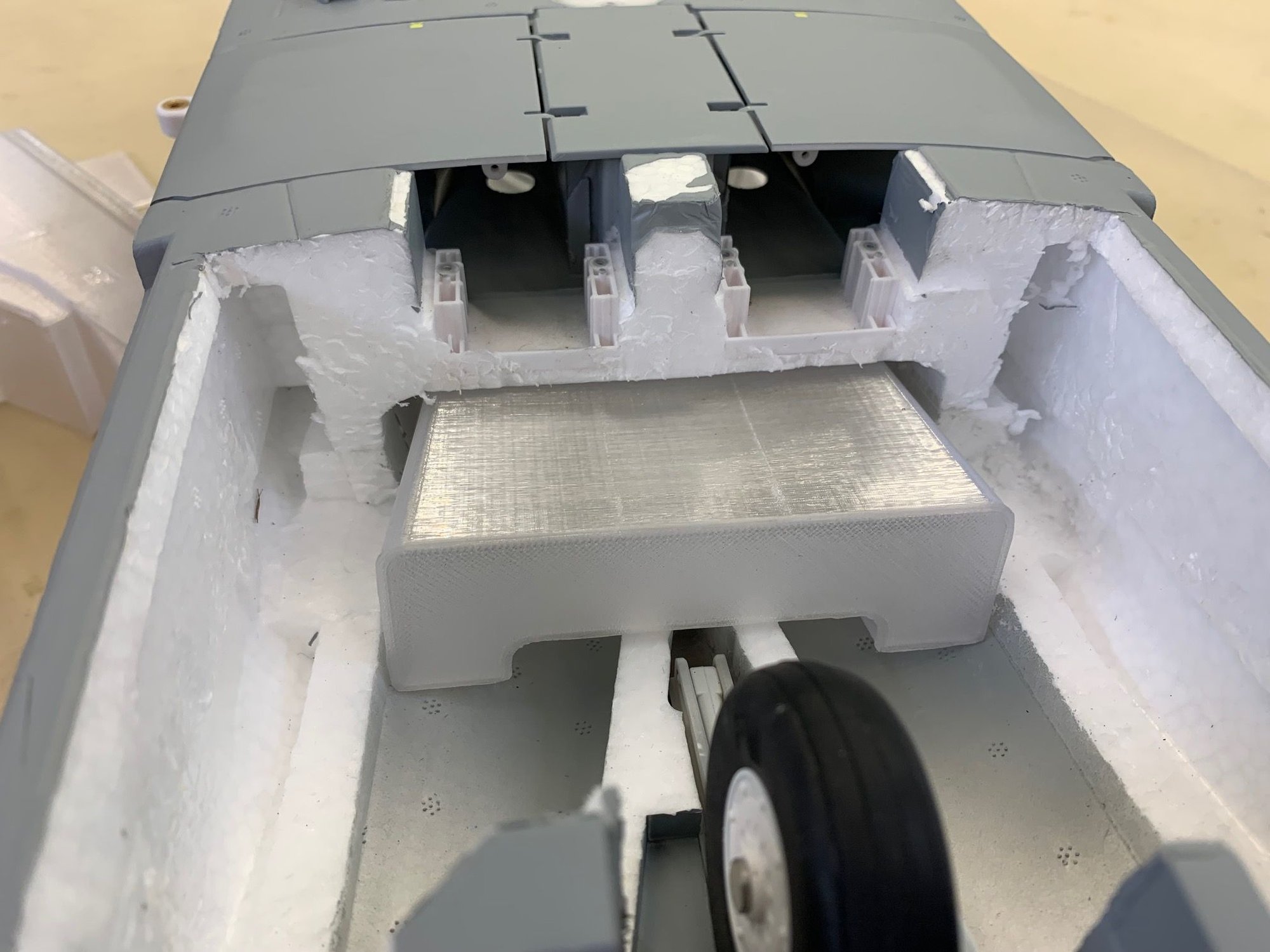
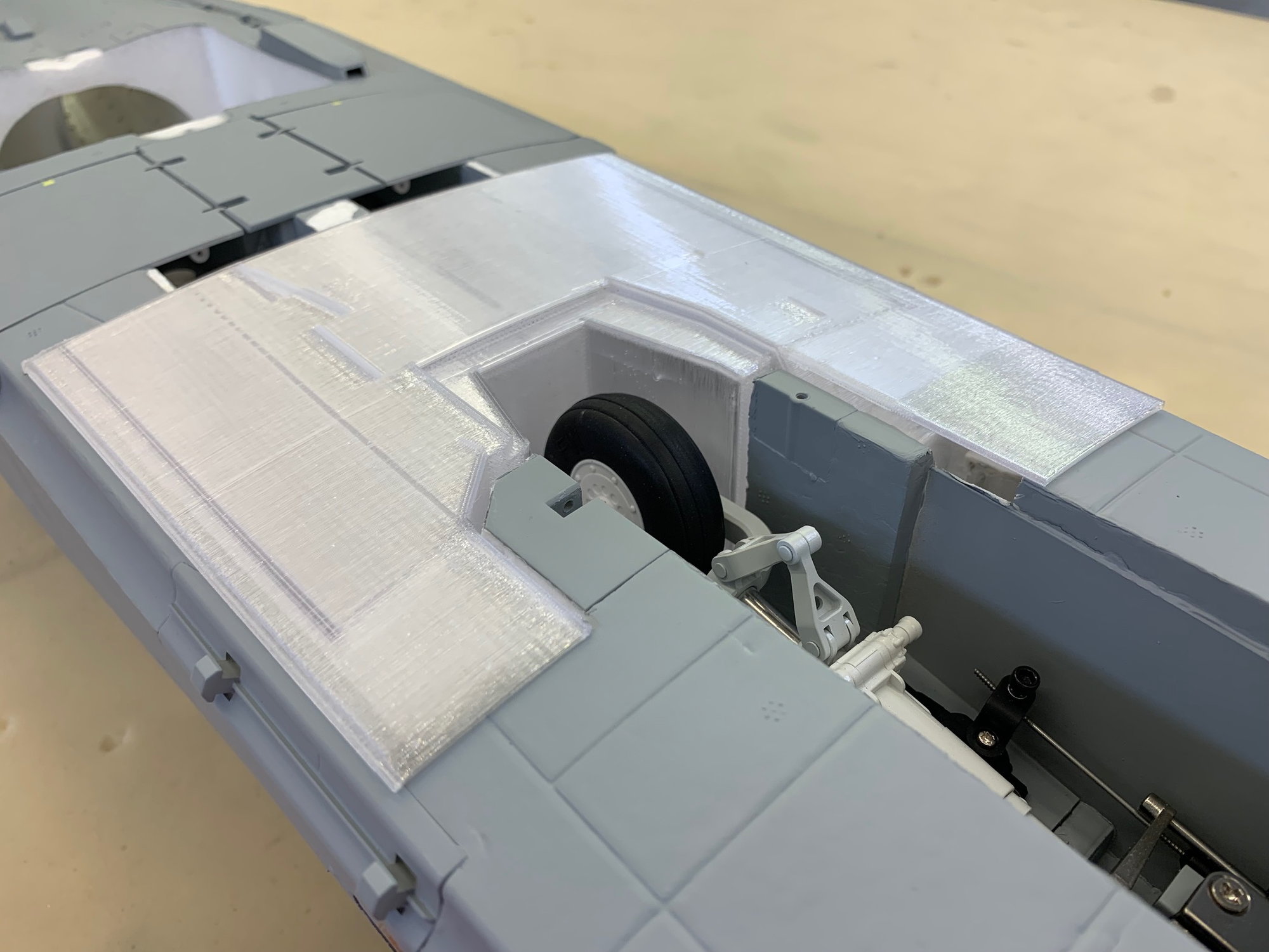
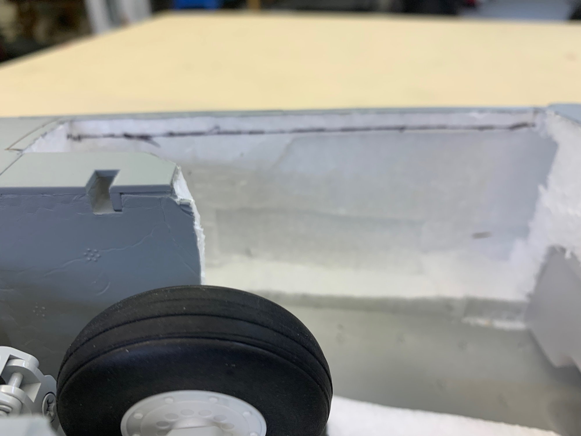
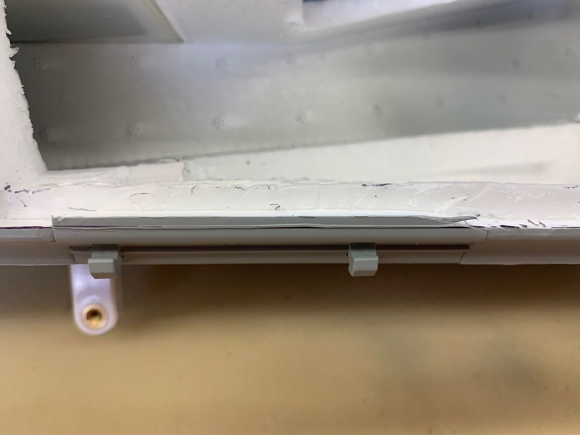
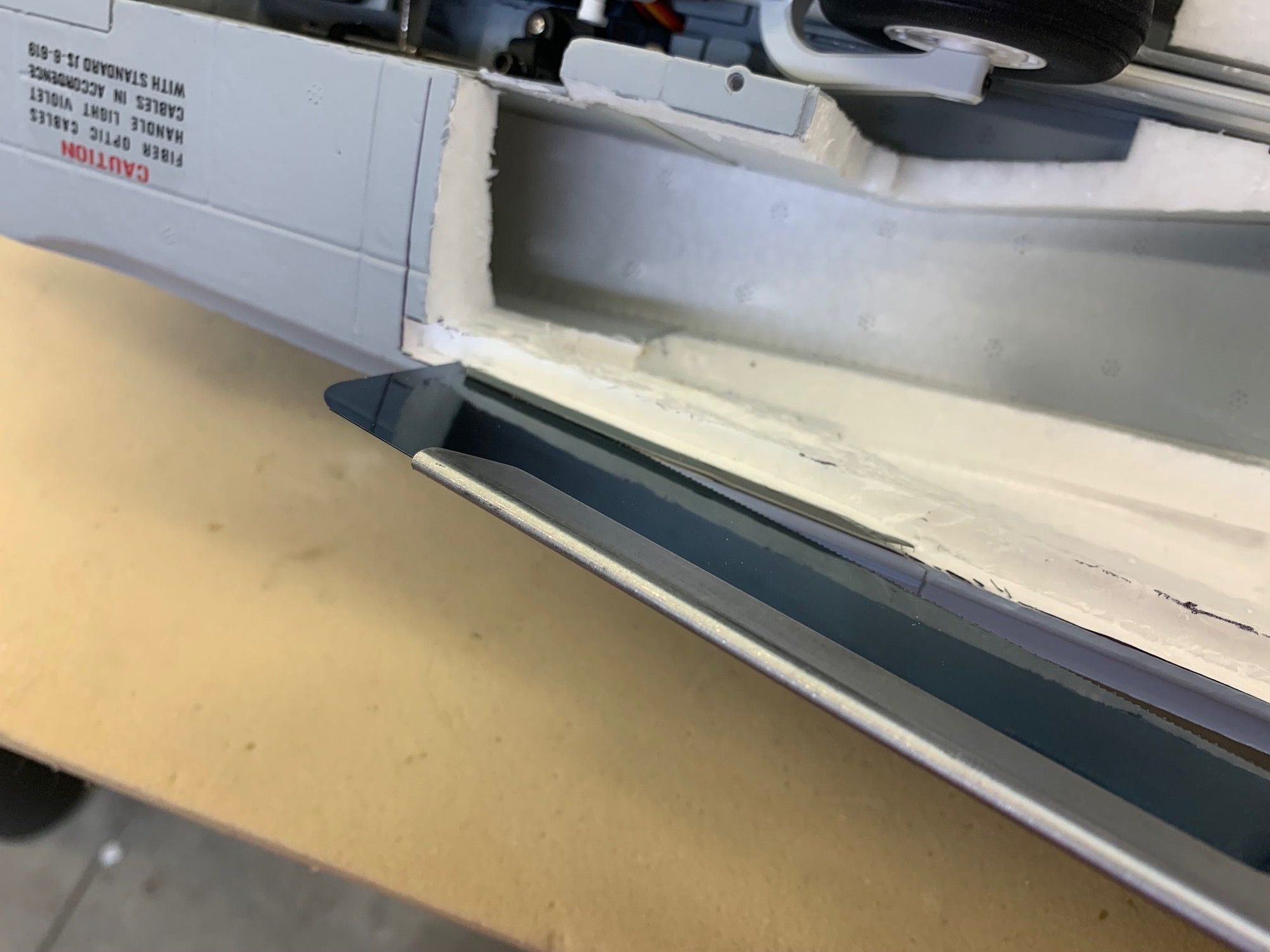
Plywood mounting rails dry fit
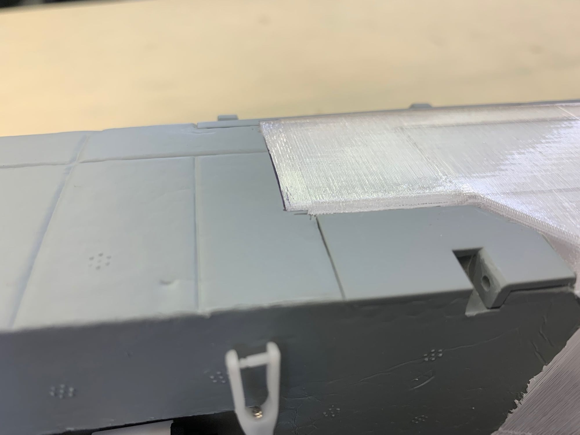
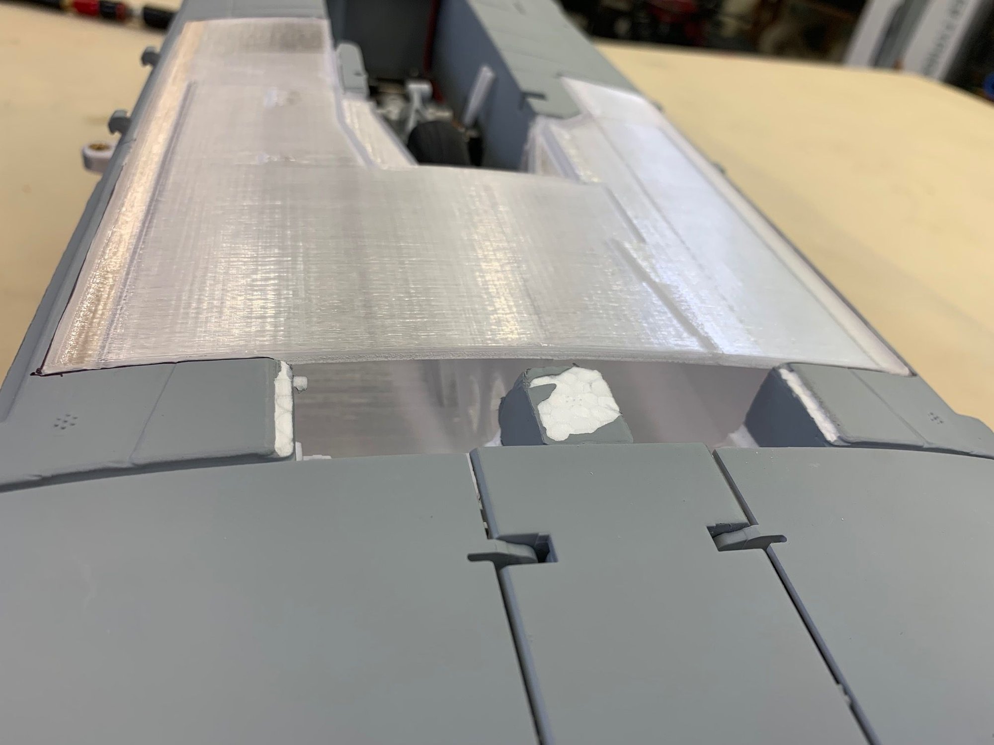
Main tank now fit flush with skin. Tank will be fastened with screws on each side. I am reprinting the tanks with the modifications and will continue with tank install when I get the new tank prints.
Last edited by Viper1GJ; 04-25-2023 at 04:56 PM.
04-25-2023, 04:54 PM
#7
Thread Starter
My Feedback: (20)
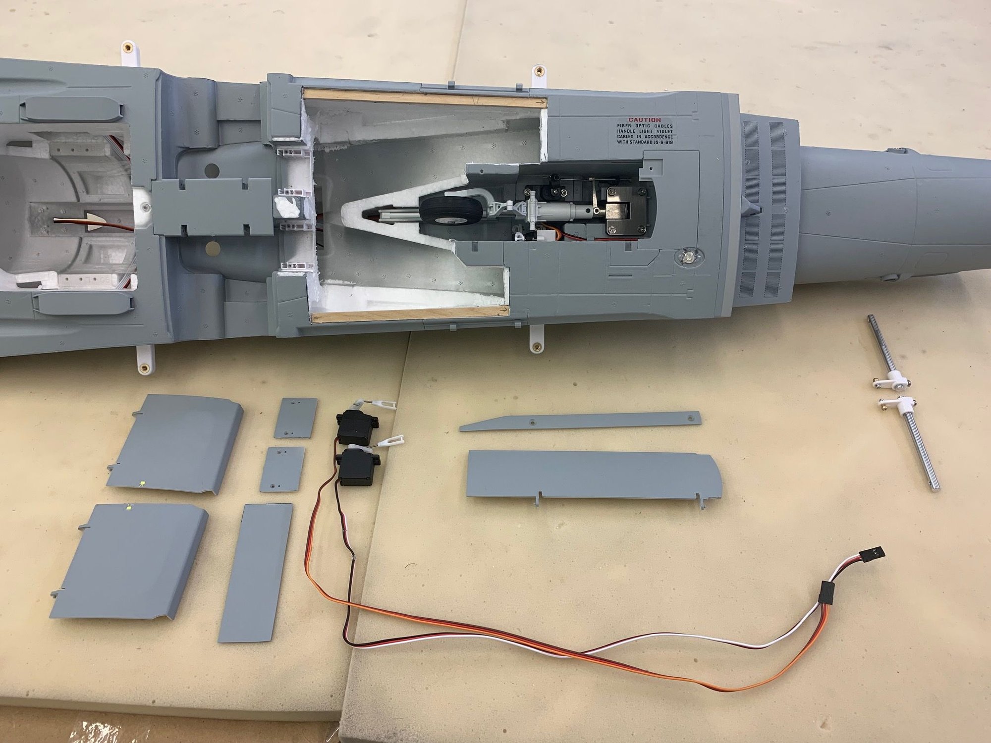
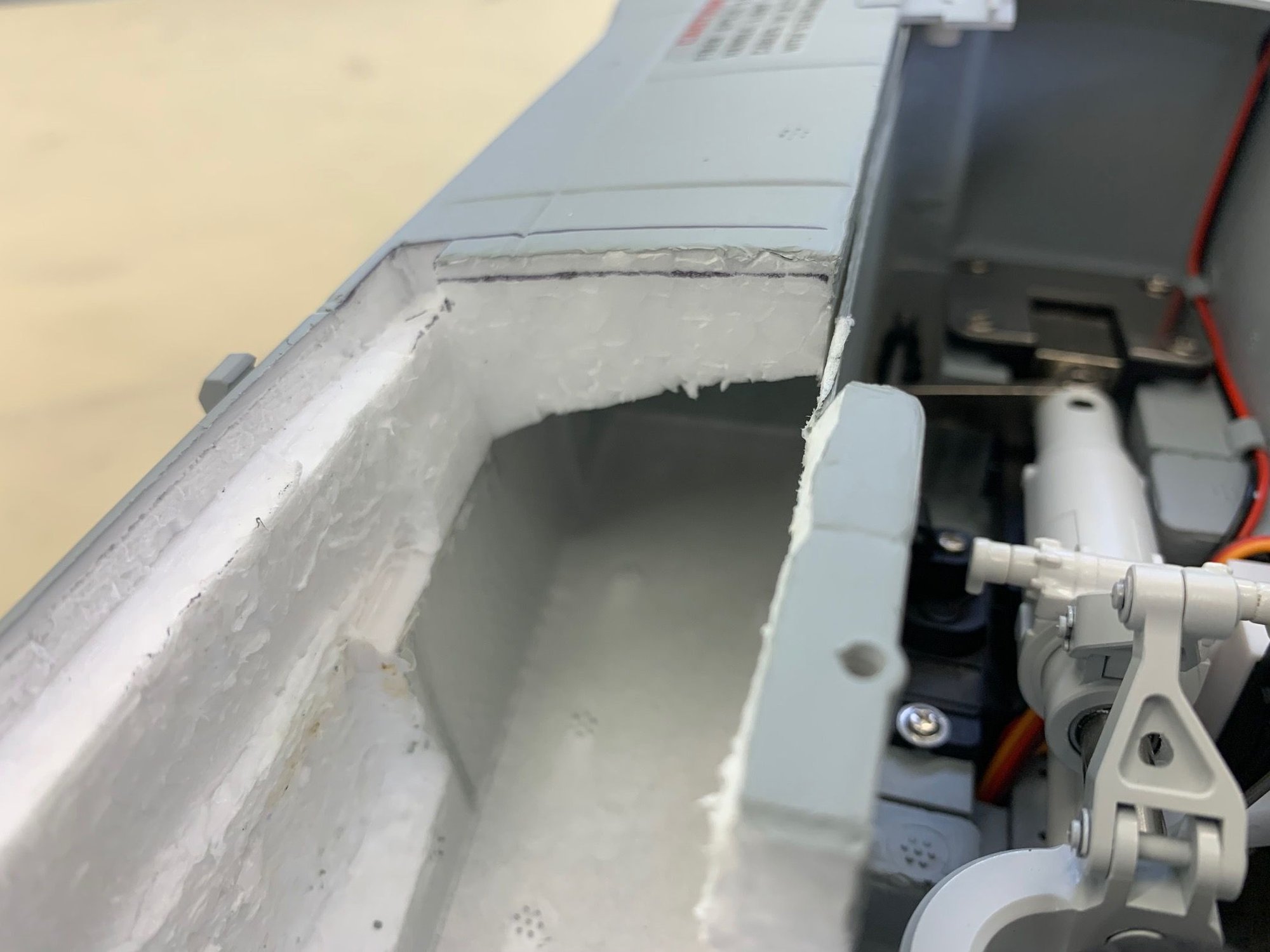
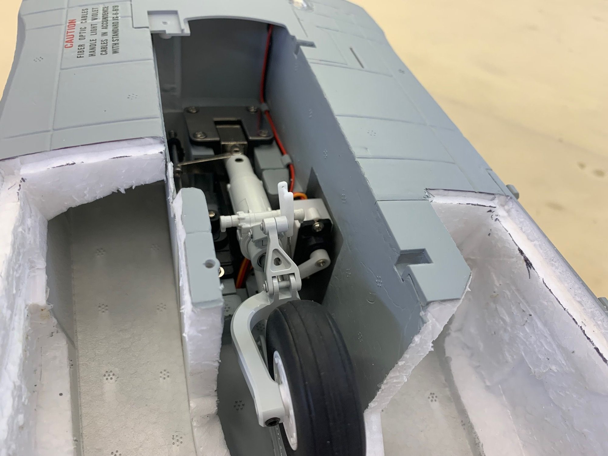
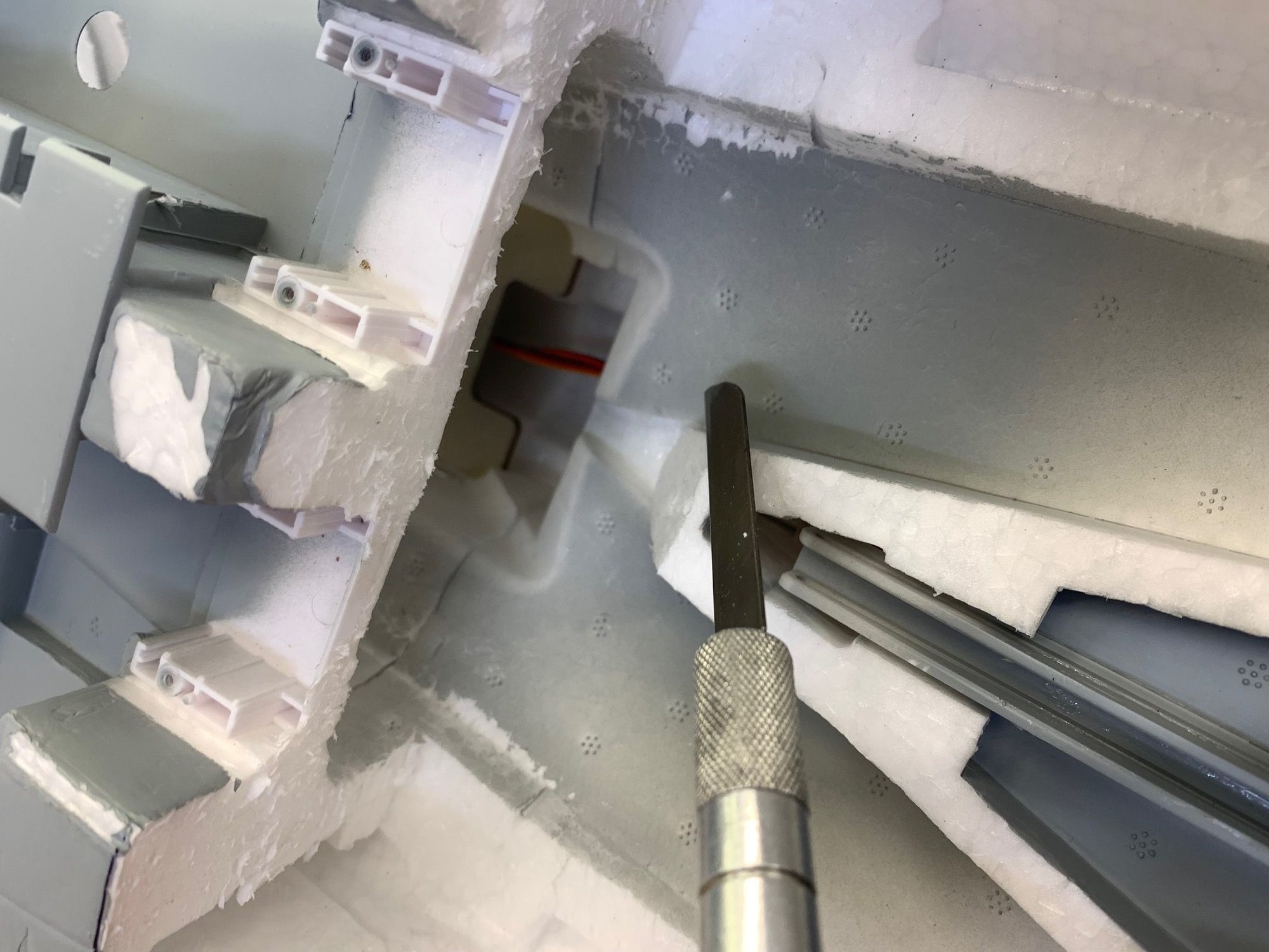
After thought photo! Here is all the stuff I suggest you remove from the jet to make working on tank cut out easy. Main gear doors, main gear door servos, mounts, and cover plate, nose gear door, nose gear door trim panel, and canard pivot rods.
04-25-2023, 05:07 PM
#8
Thread Starter
My Feedback: (20)
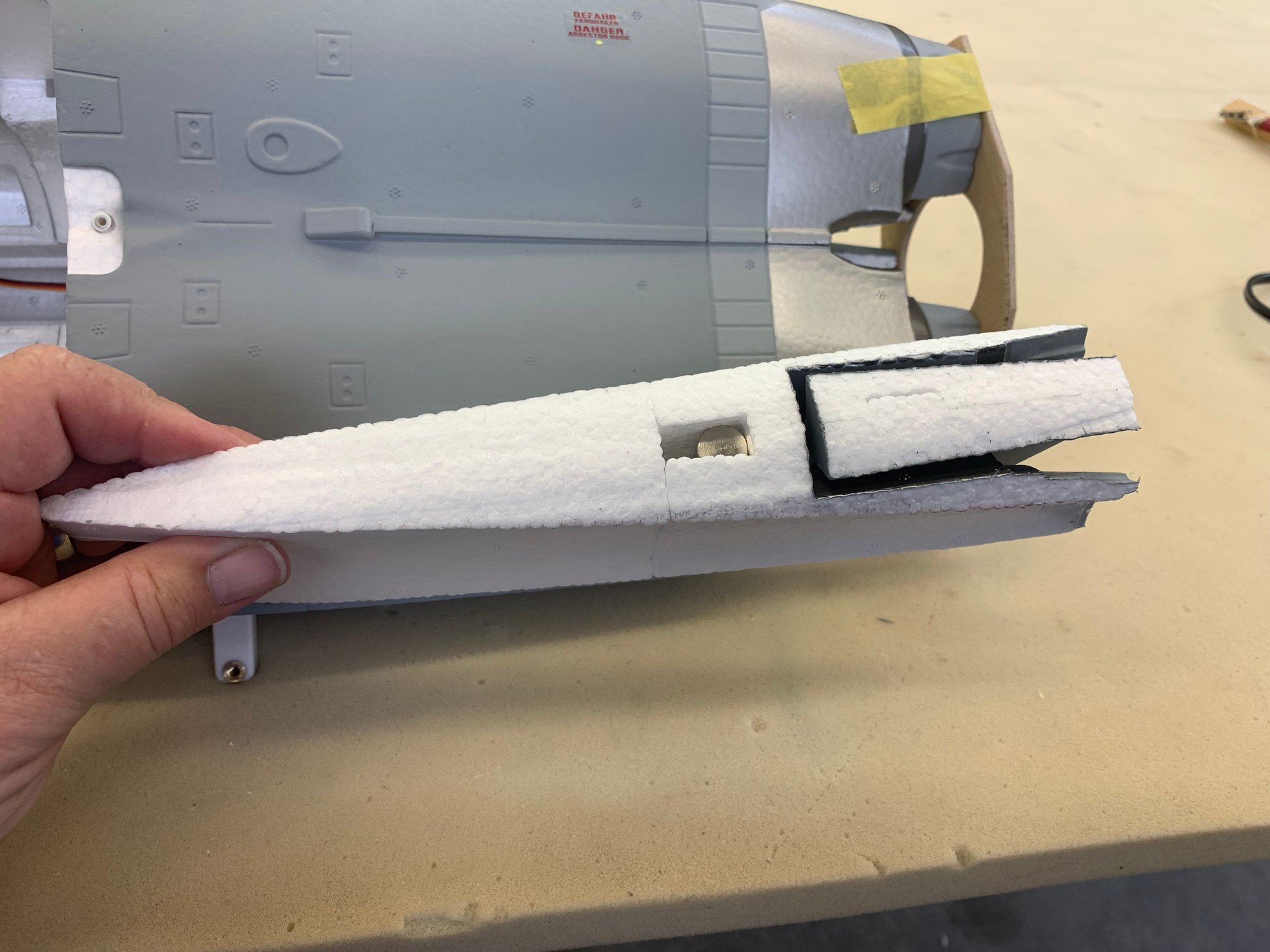
Preparing to hot wire cut the pipe tunnel
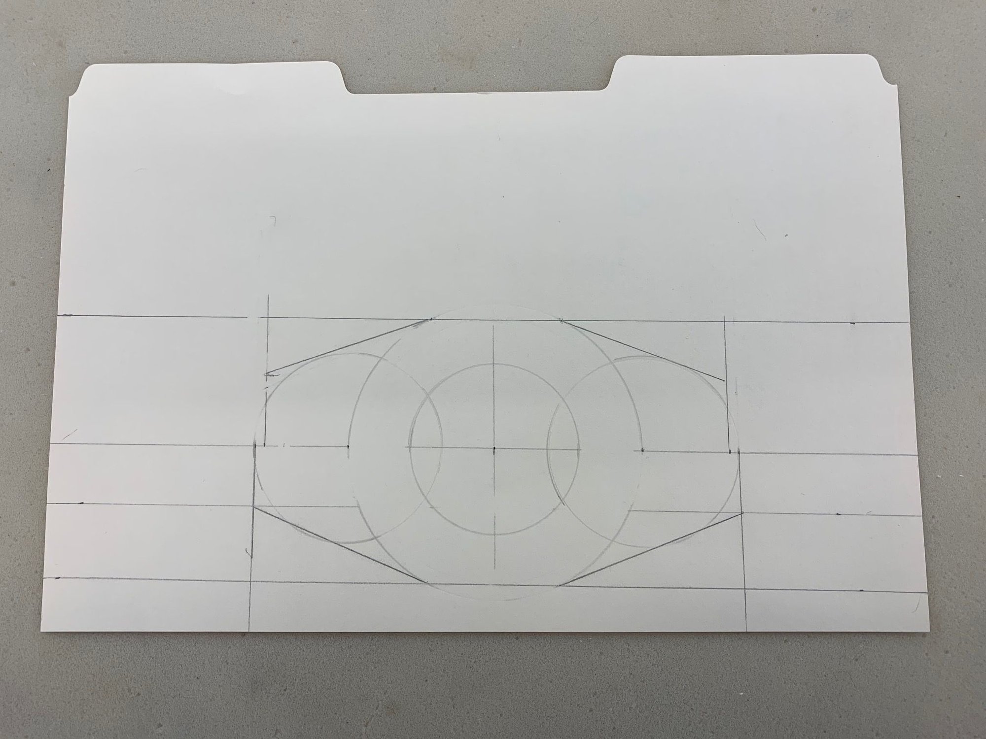
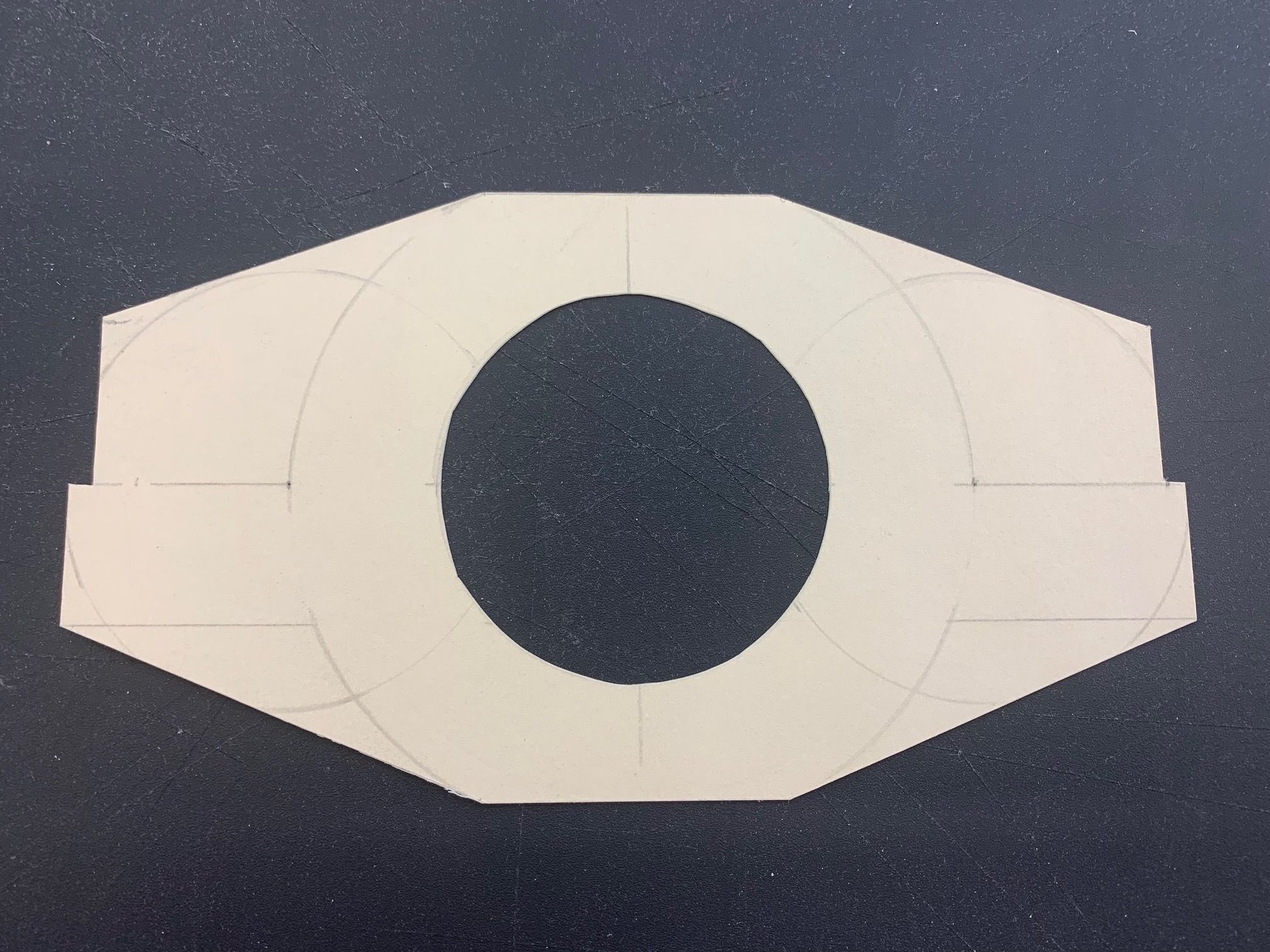
Template transferred to plywood cutting template
Rear end of tail plug cut off to allow hot wire to cut curved pipe tunnel on bottom. In hind site I would not do this again and would just hand cut the bottom of the plug with a knife and sand to shape after pipe installed.

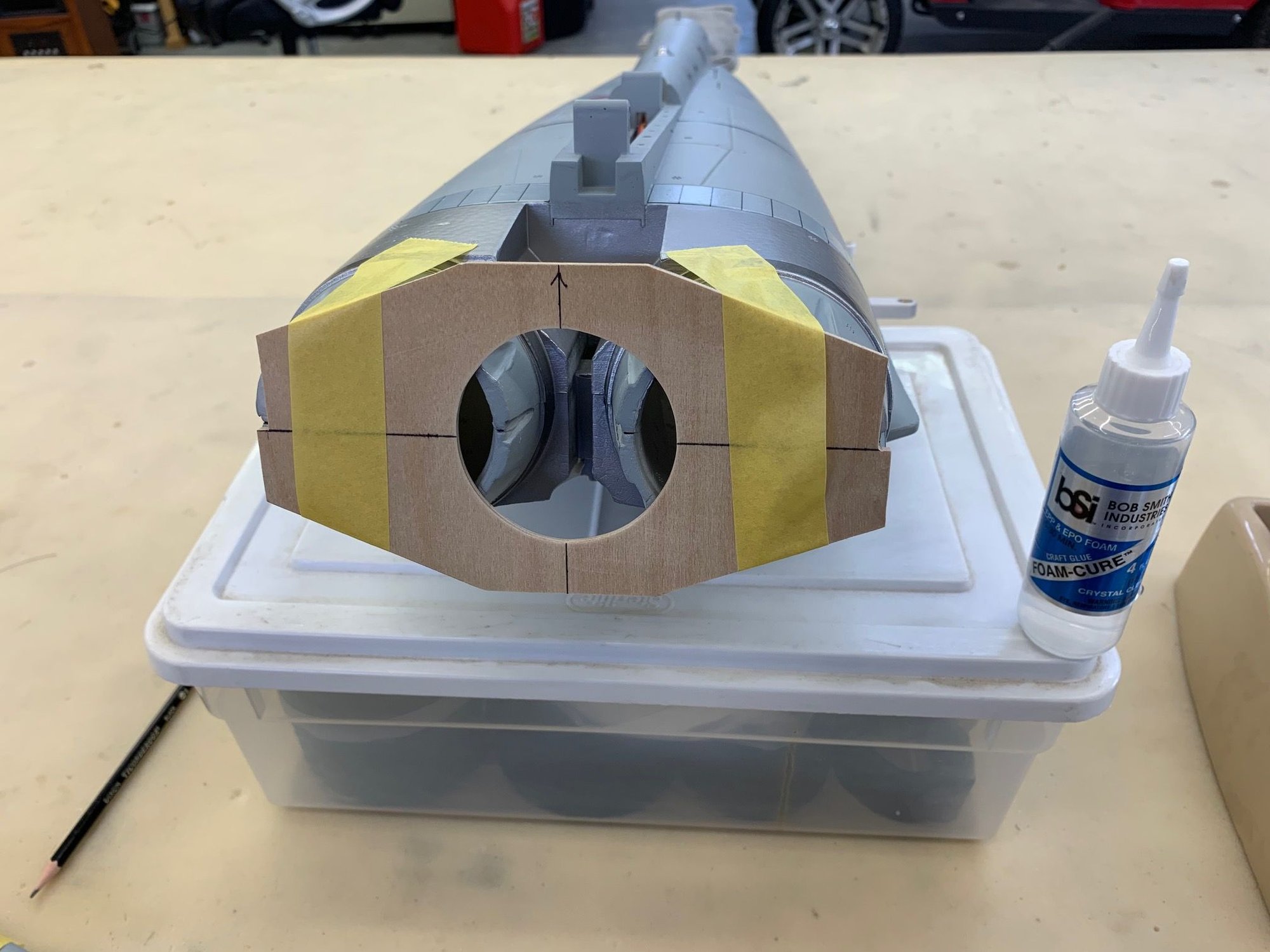
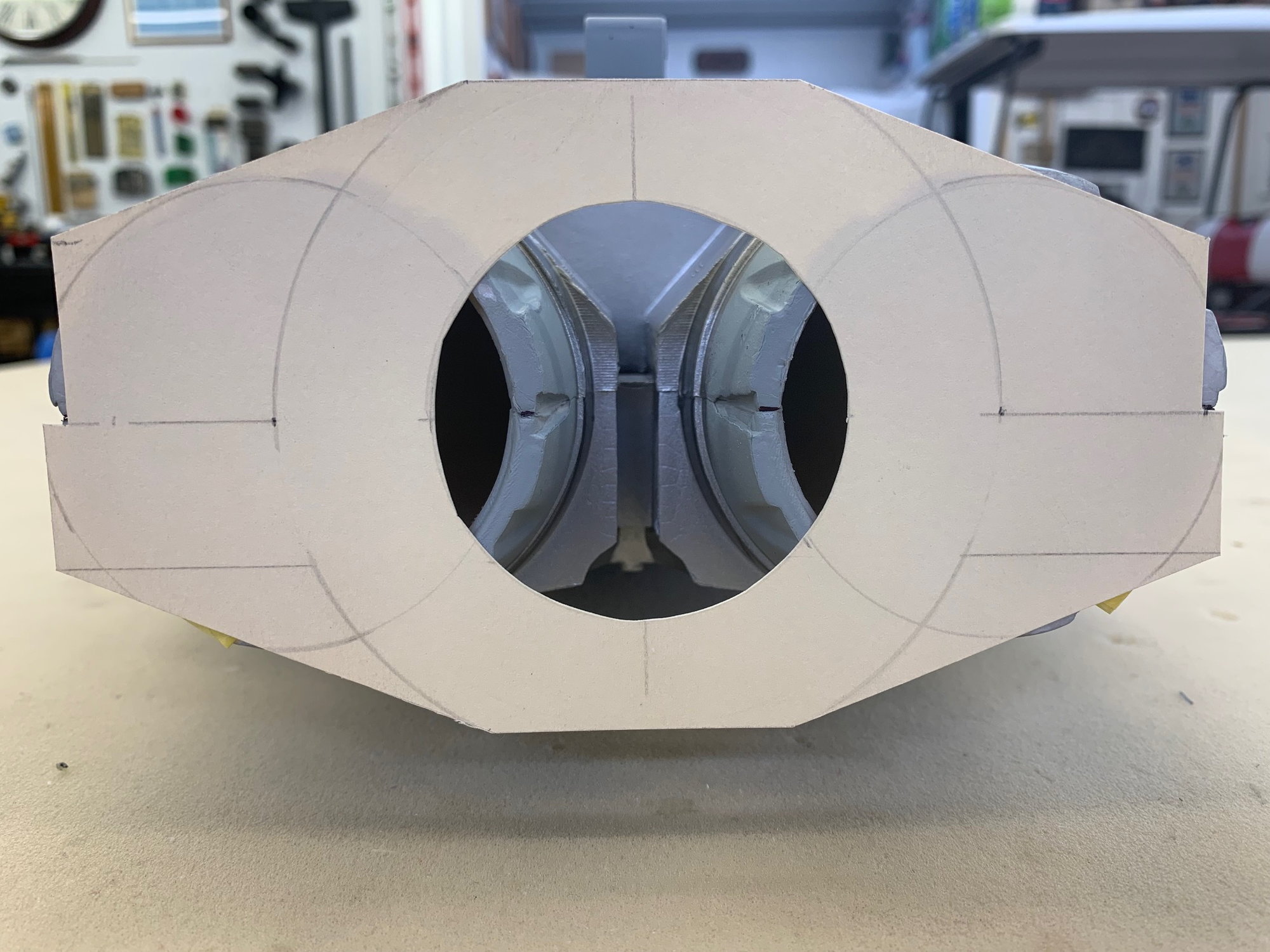
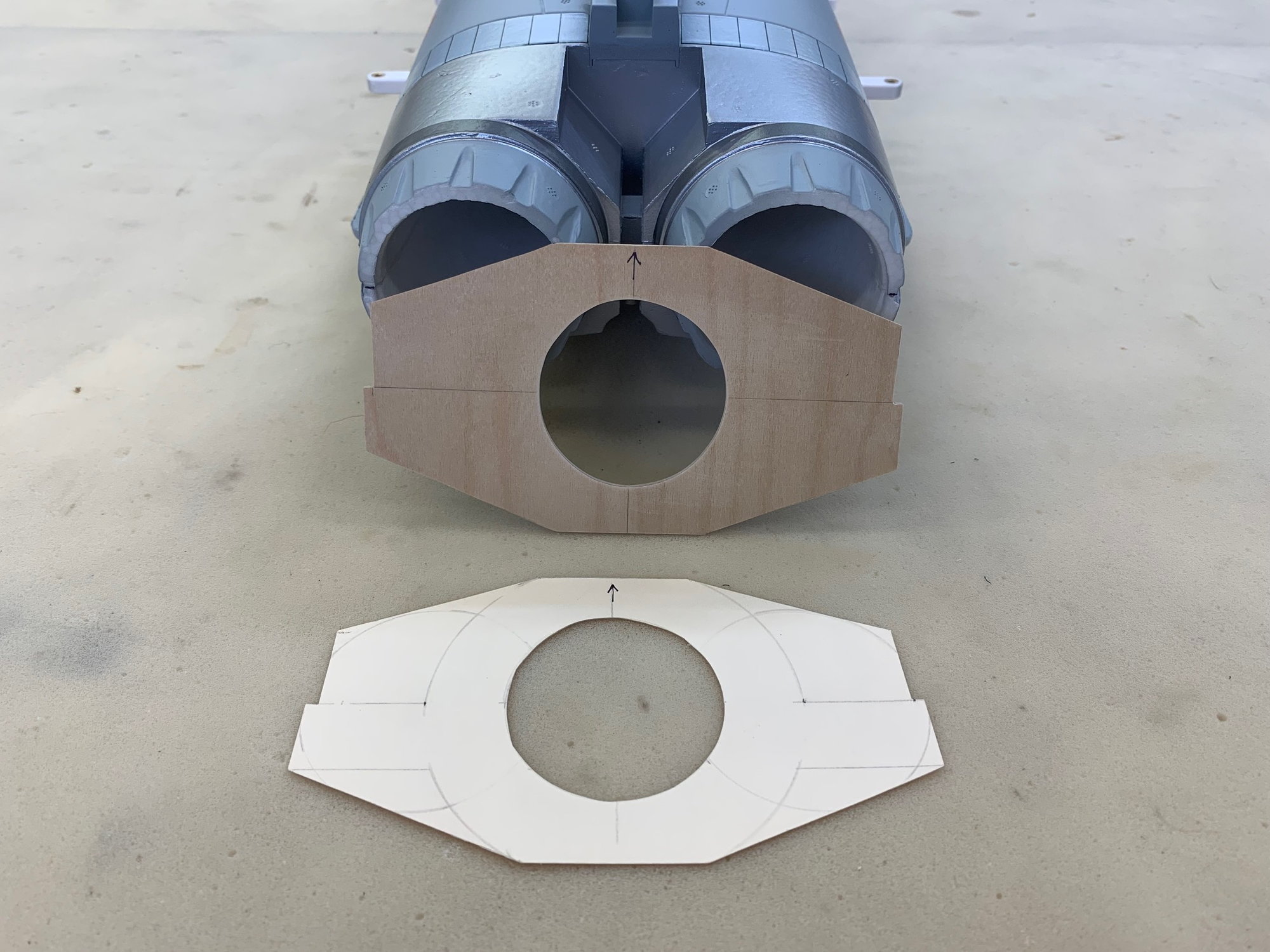
Cutting template glued and taped to foam nozzles
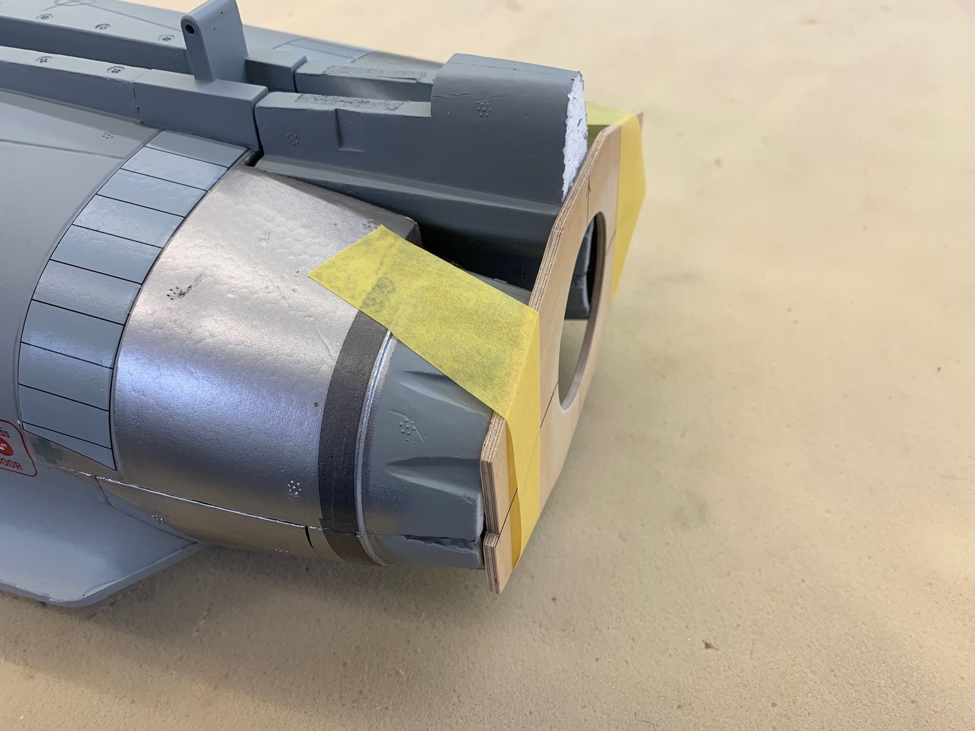
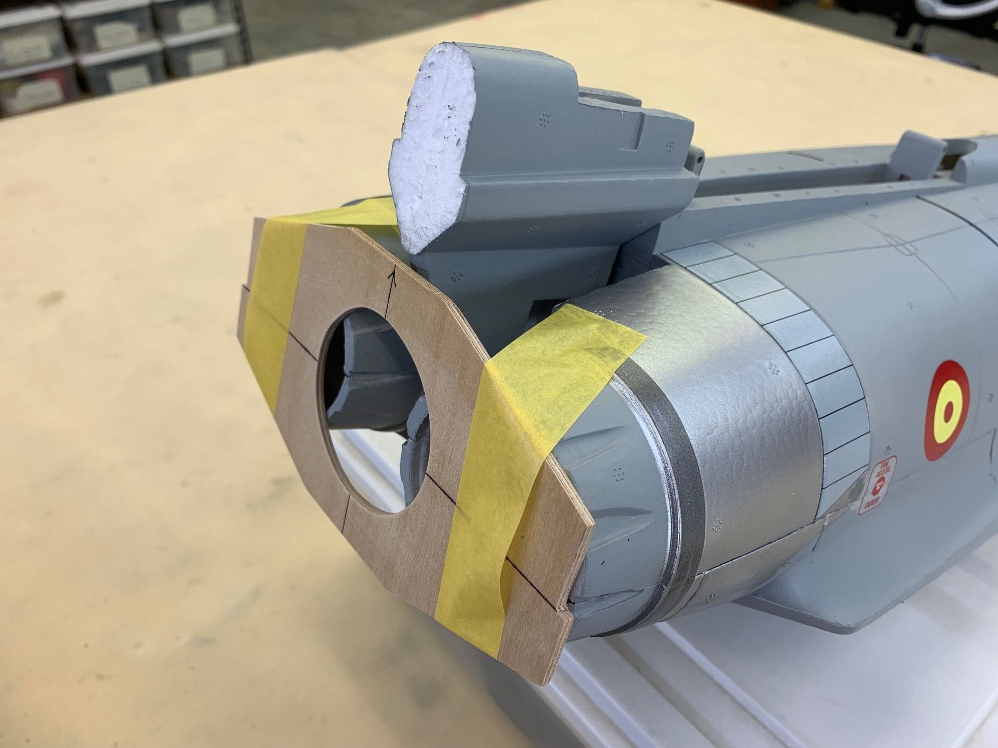
Tail plug inserted in front of template

Ready to cut foam tunnel
Template transferred to plywood cutting template
Rear end of tail plug cut off to allow hot wire to cut curved pipe tunnel on bottom. In hind site I would not do this again and would just hand cut the bottom of the plug with a knife and sand to shape after pipe installed.
Cutting template glued and taped to foam nozzles
Tail plug inserted in front of template
Ready to cut foam tunnel
04-25-2023, 05:23 PM
#9
Thread Starter
My Feedback: (20)
Hot wire cutting pipe tunnel
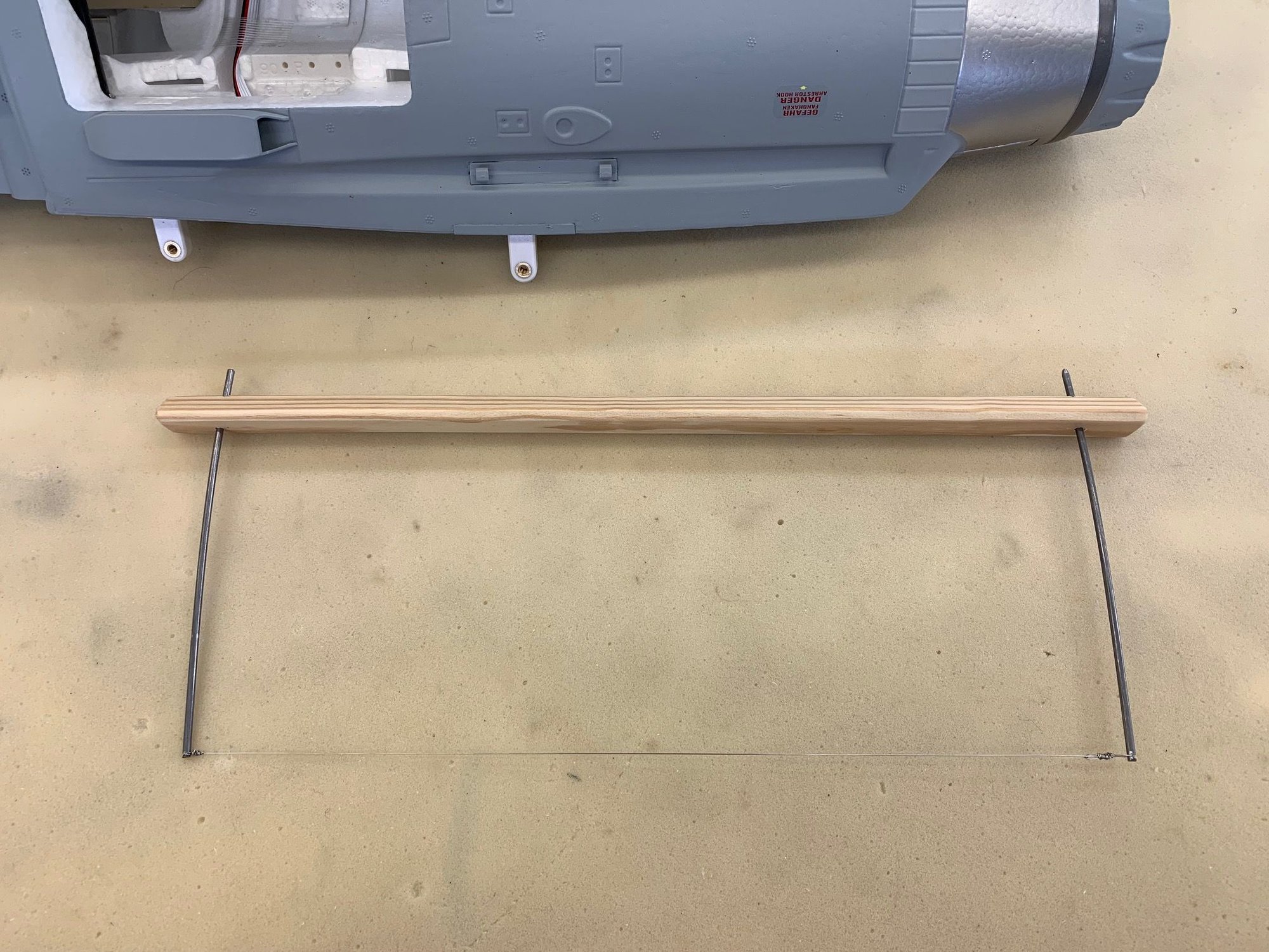
All my larger cutting bows were too big to fit so I made a small one. I attached the cutting wire to the very bottom of the spring wires to be able to get the wire as close the the foam as possible at the front of the tunnel
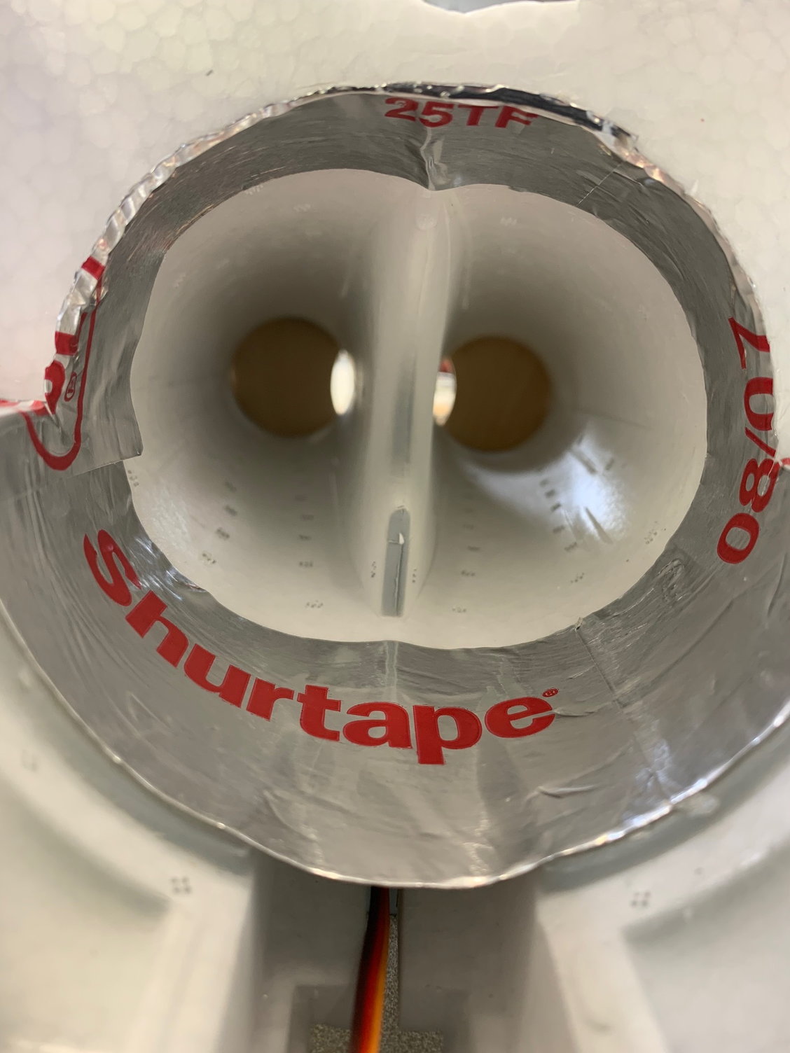
I lined the front of the tunnel with HVAC tape to allow the cutting wire to slide over the tape and make the largest possible cut at the front of the tunnel
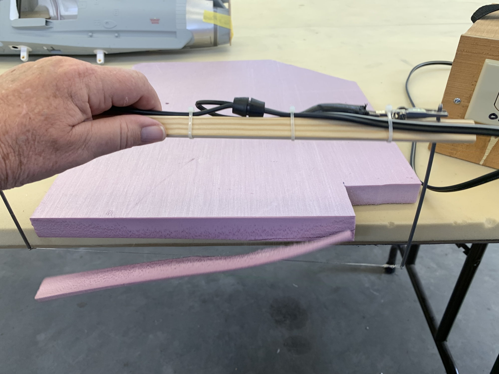
Scrap foam cutting to adjust the wire temp and power setting
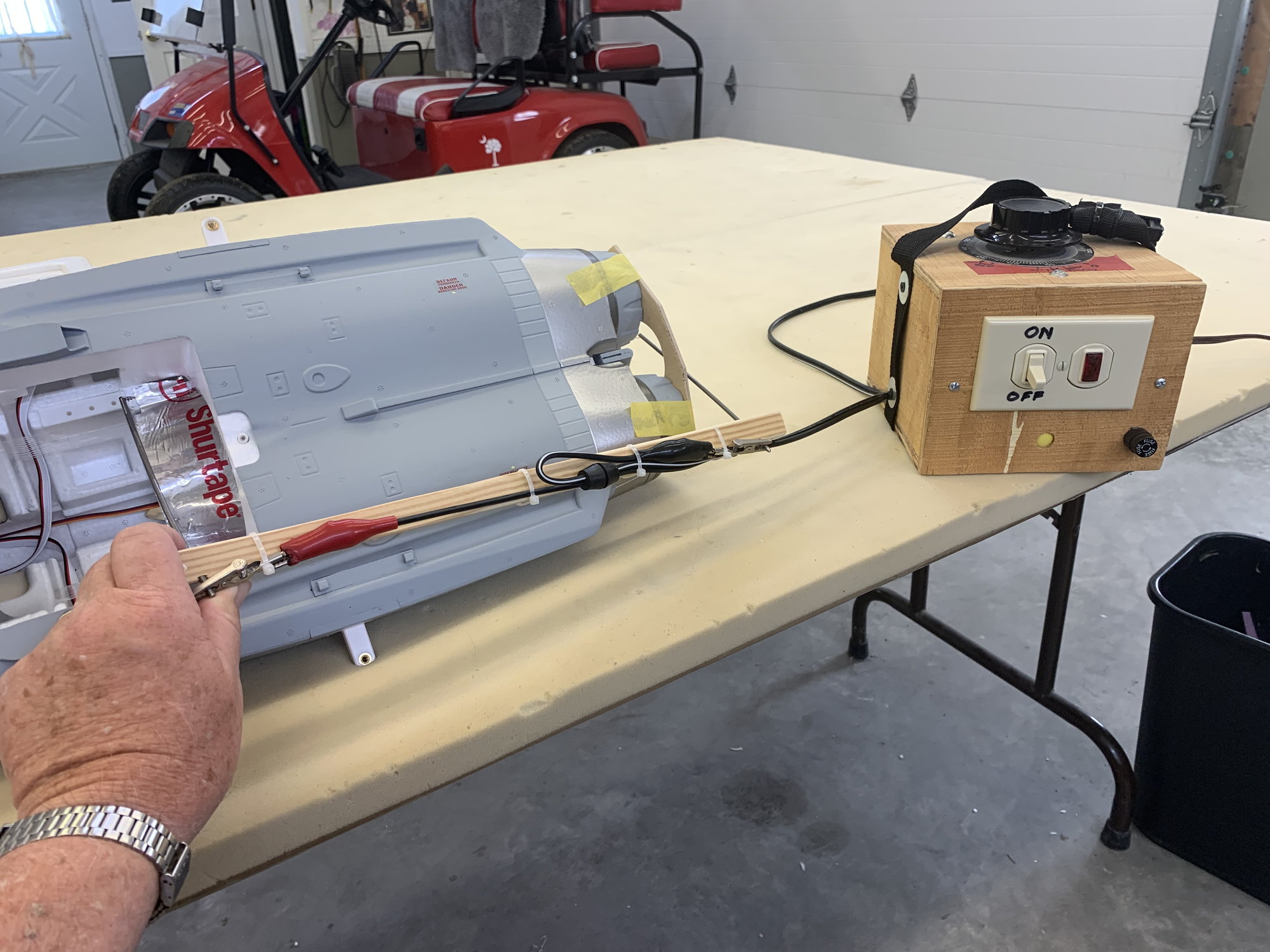
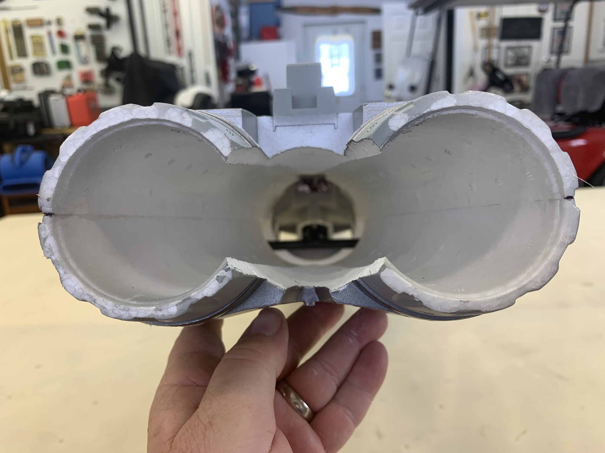
Cutting bow in position inside the tunnel. The object is to cut out the duct separator and leave a smooth cut surface with the aft end the correct size for my homemade double wall pipe.
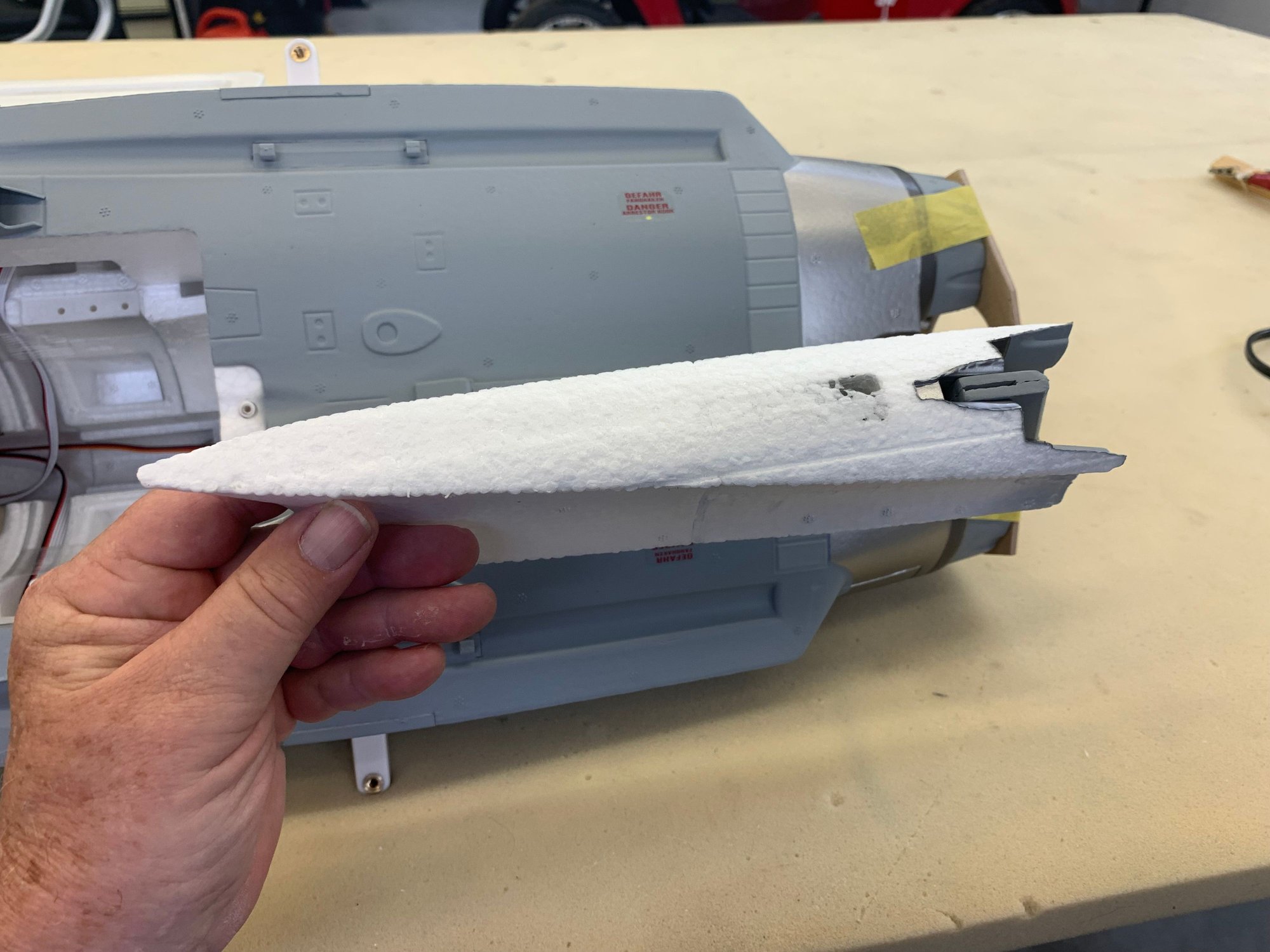
Cut complete and separator removed
I found a metal weight slug in the tail. I'm glad the cutting wire did not hit it.

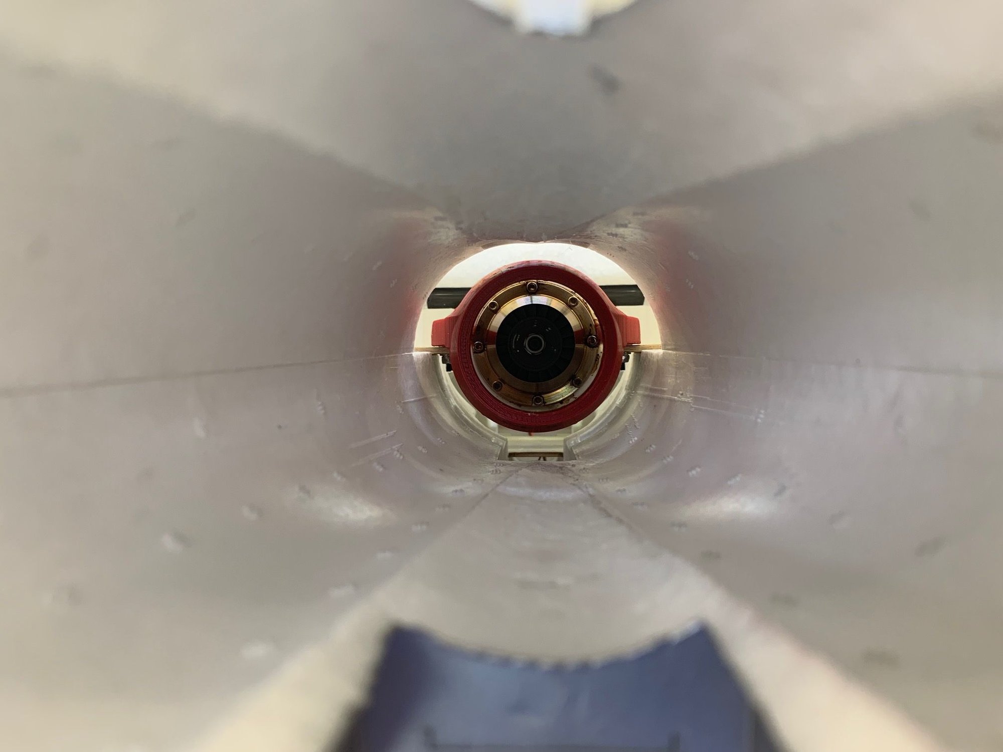
Inside view of pipe tunnel. There is plenty of room in this one.
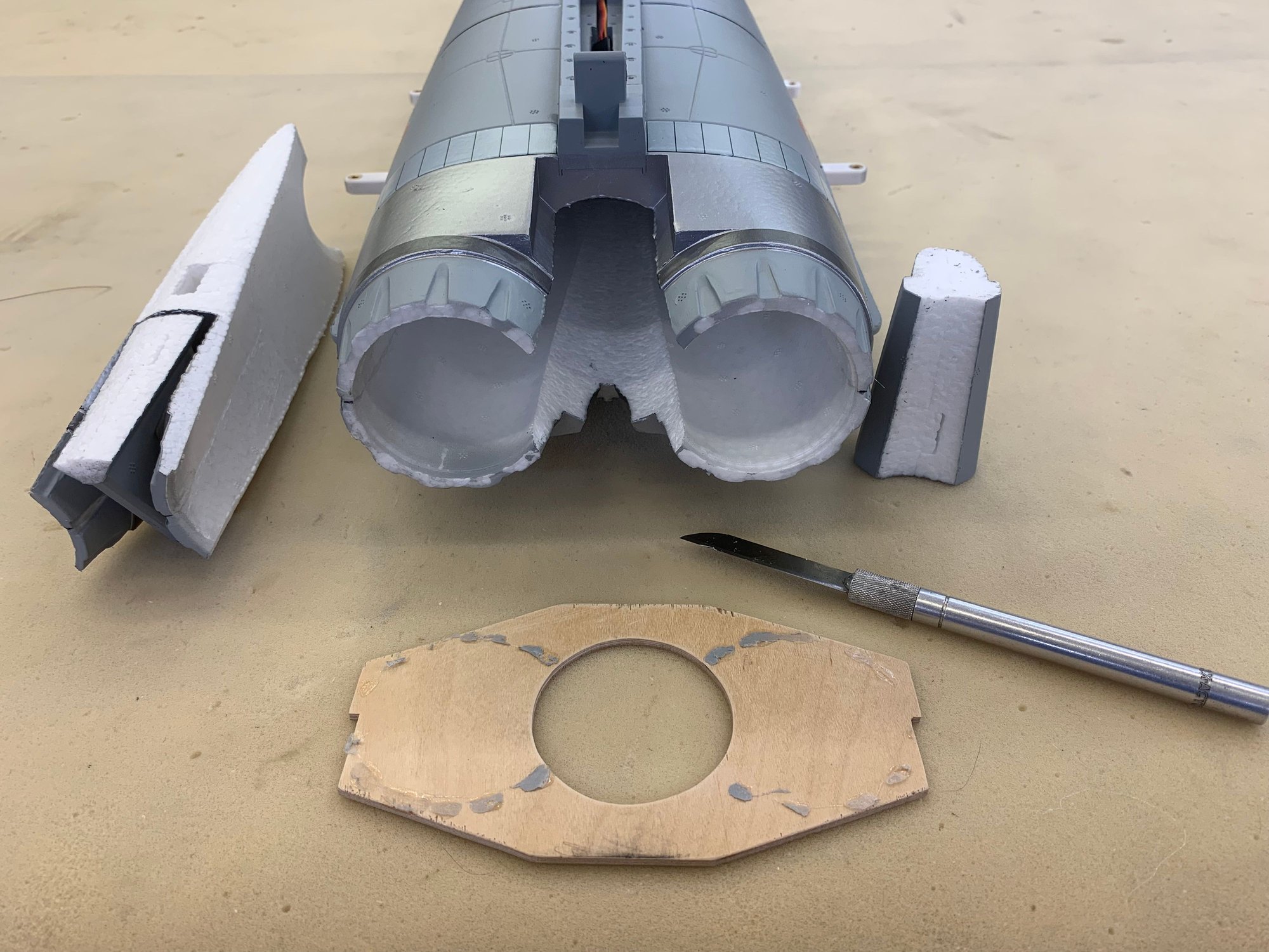
Rear cutting template removed from nozzles with knife
View from rear
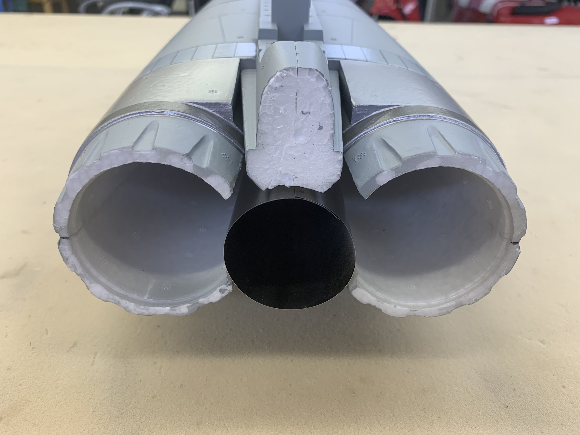
Inner pipe test fit just for looks.
All my larger cutting bows were too big to fit so I made a small one. I attached the cutting wire to the very bottom of the spring wires to be able to get the wire as close the the foam as possible at the front of the tunnel
I lined the front of the tunnel with HVAC tape to allow the cutting wire to slide over the tape and make the largest possible cut at the front of the tunnel
Scrap foam cutting to adjust the wire temp and power setting
Cutting bow in position inside the tunnel. The object is to cut out the duct separator and leave a smooth cut surface with the aft end the correct size for my homemade double wall pipe.
Cut complete and separator removed
I found a metal weight slug in the tail. I'm glad the cutting wire did not hit it.
Inside view of pipe tunnel. There is plenty of room in this one.
Rear cutting template removed from nozzles with knife
View from rear
Inner pipe test fit just for looks.
04-25-2023, 05:32 PM
#10
Thread Starter
My Feedback: (20)
Turbine mounting
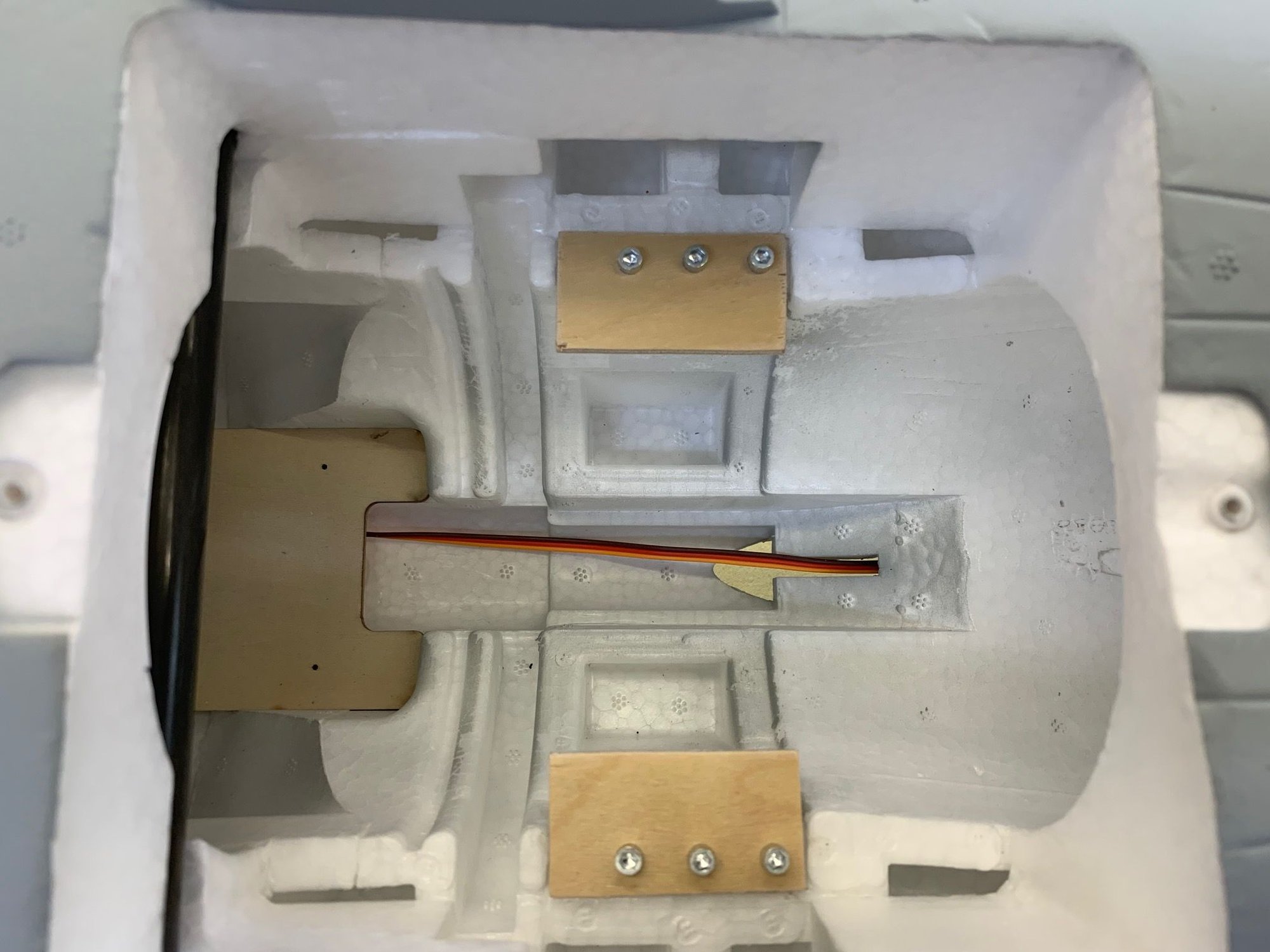
The turbine can not go any further forward because of the main wing spar tube. I made simple plywood plates using the existing EDF mounts.
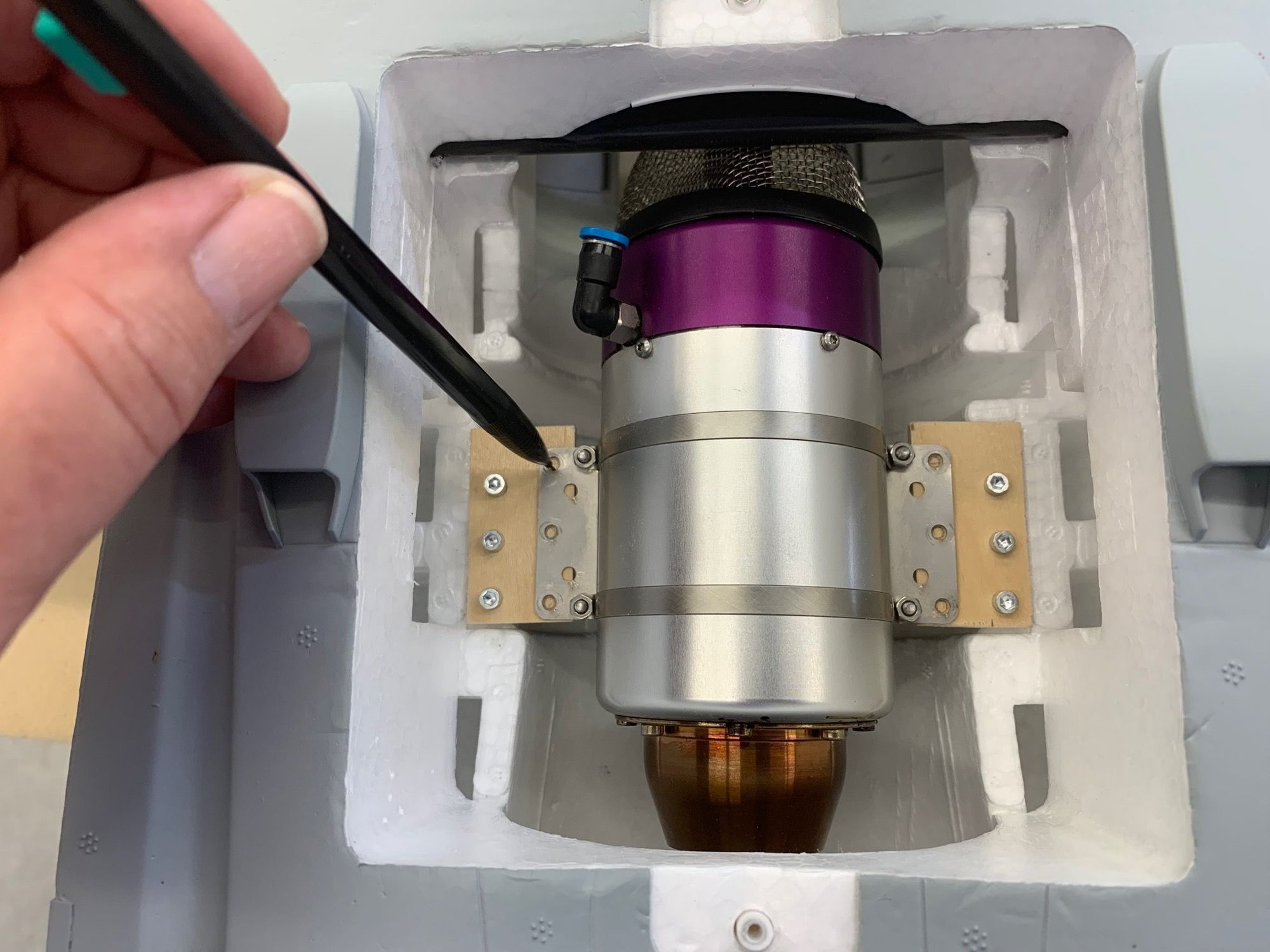
Aft turbine mount holes reserved for the pipe bell cone
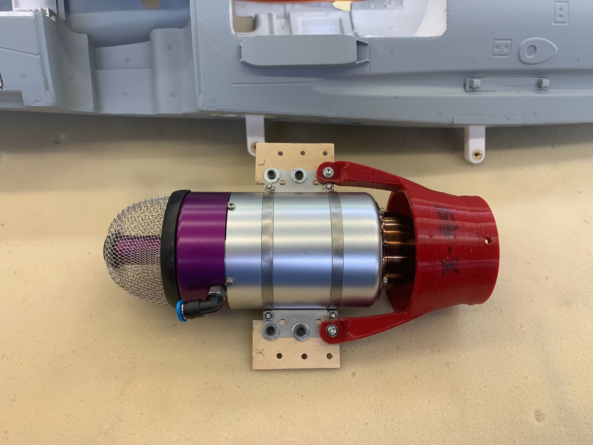
Heat treated 3D printed pipe cone will be used. This is a mockup.
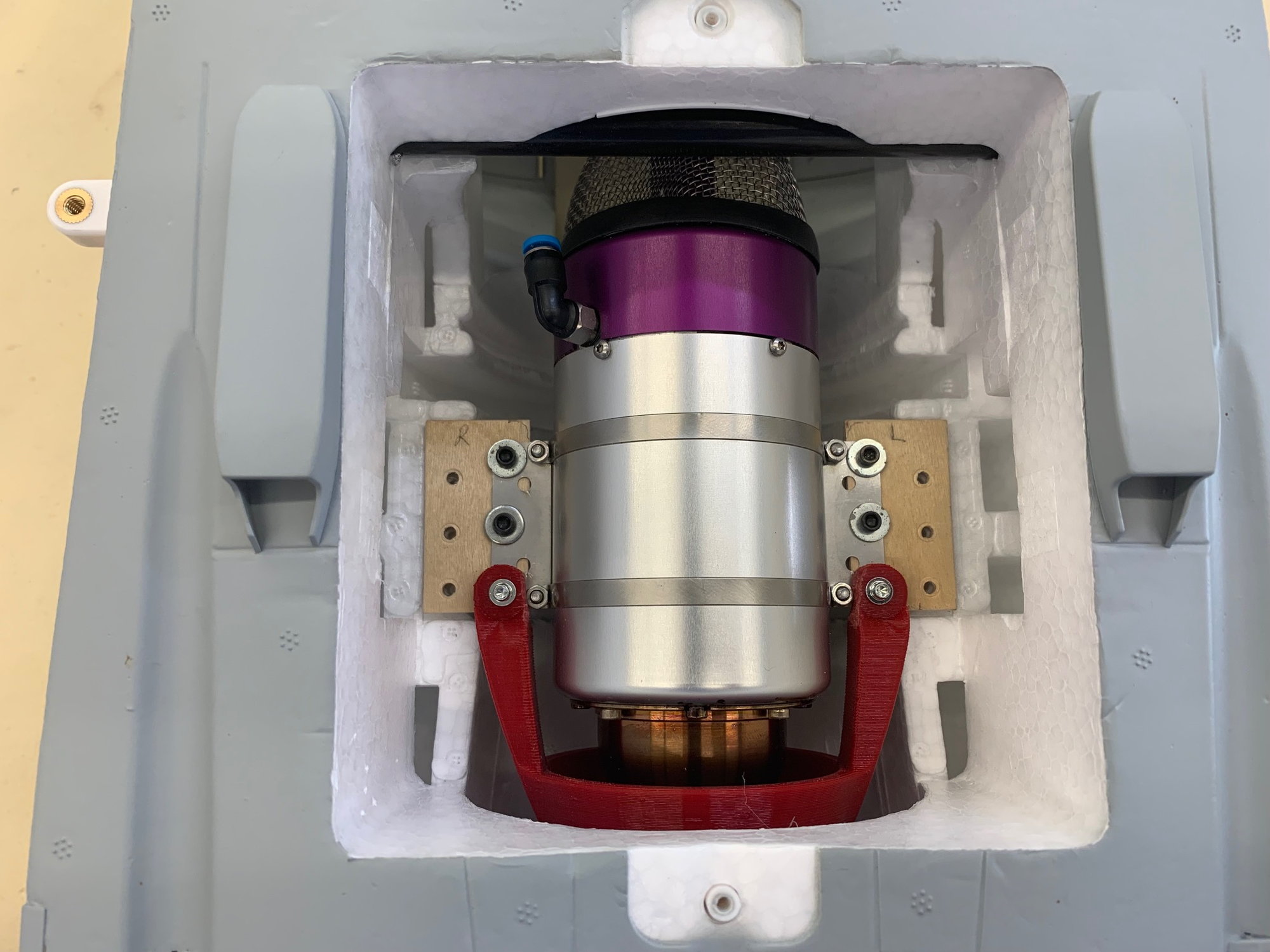
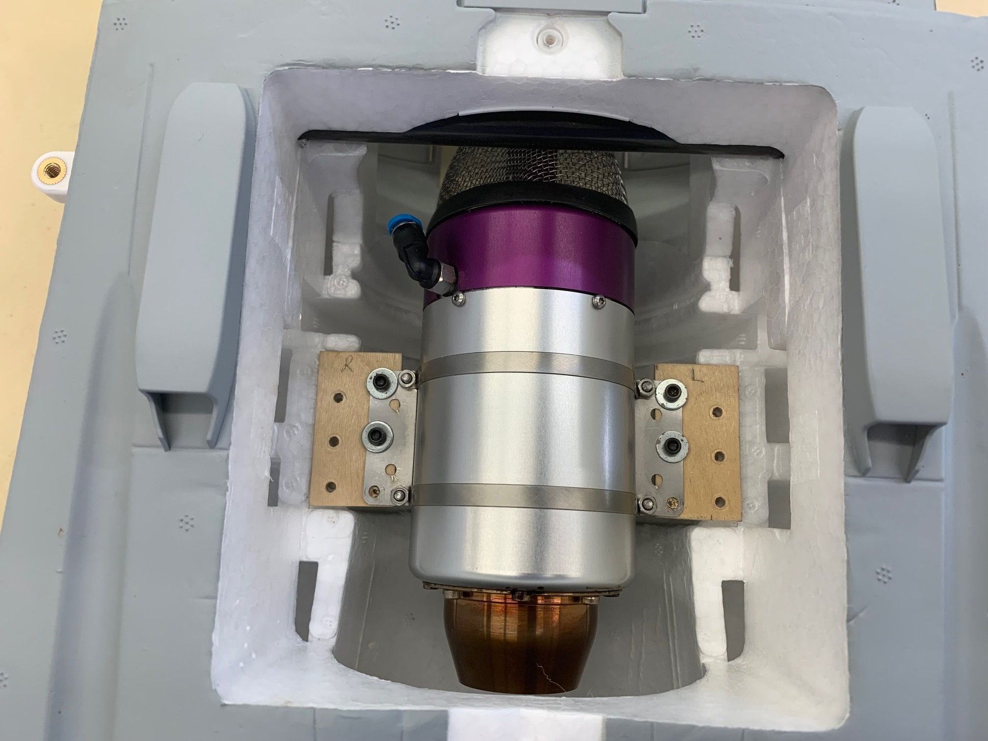
Turbine centered in pipe cone
The turbine can not go any further forward because of the main wing spar tube. I made simple plywood plates using the existing EDF mounts.
Aft turbine mount holes reserved for the pipe bell cone
Heat treated 3D printed pipe cone will be used. This is a mockup.
Turbine centered in pipe cone
04-25-2023, 05:45 PM
#11
Thread Starter
My Feedback: (20)
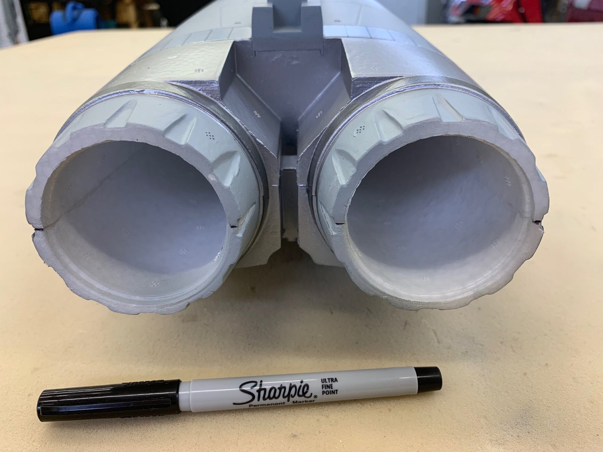
Cutting nozzles
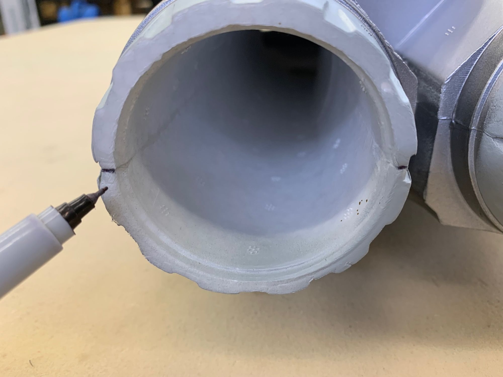
Mark outside center of each nozzle

Center template and mark intersection of cutting hole and nozzle edge
Cut lines marked with tape

Cuts made with scroll saw

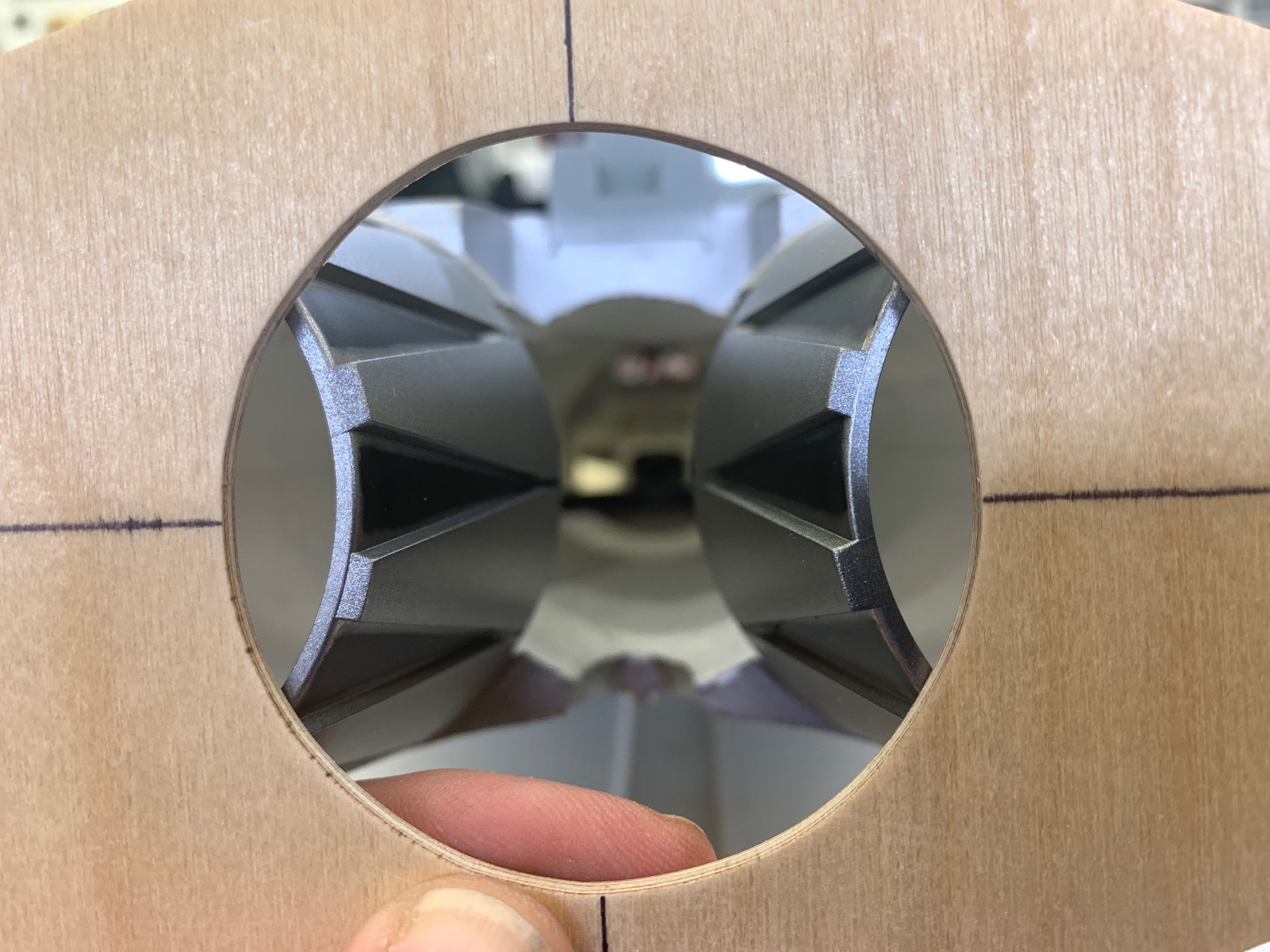
Dry fit with inner pipe to just look
Looks OK
Mark outside center of each nozzle
Center template and mark intersection of cutting hole and nozzle edge
Cut lines marked with tape
Cuts made with scroll saw
Dry fit with inner pipe to just look
Looks OK
04-25-2023, 06:03 PM
#12
Thread Starter
My Feedback: (20)
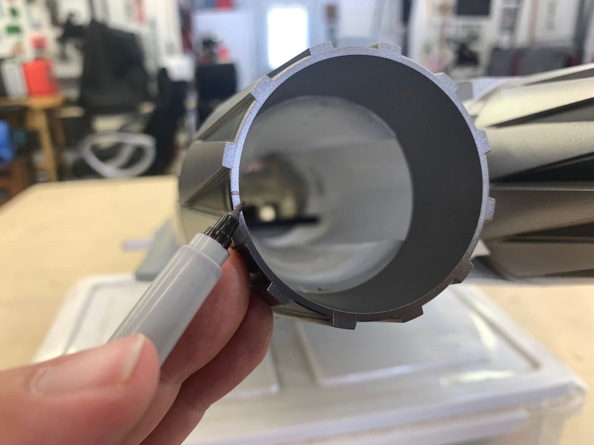
Finishing pipe
I had the luxury of having the inner pipe already made by Keith. All I had to do was make the outer pipe.
The inner pipe and 3D cones are 46mm. The outer pipe is 54mm. With shims in the tail the rear hole in the cutting template was 58mm. For more detailed info on how I make the pipes see here:
Turbine Conversion Of 80mm Freewing A-10 To Single X-45 Turbine Post # 4-7

Cooking the HTPLA cones at 200 degrees for one hour

Cutting the outer pipe from roofing aluminum
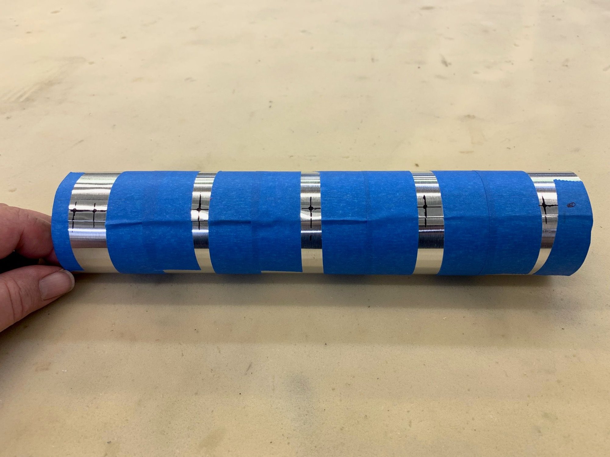
Outer pipe rolled, taped, and marked
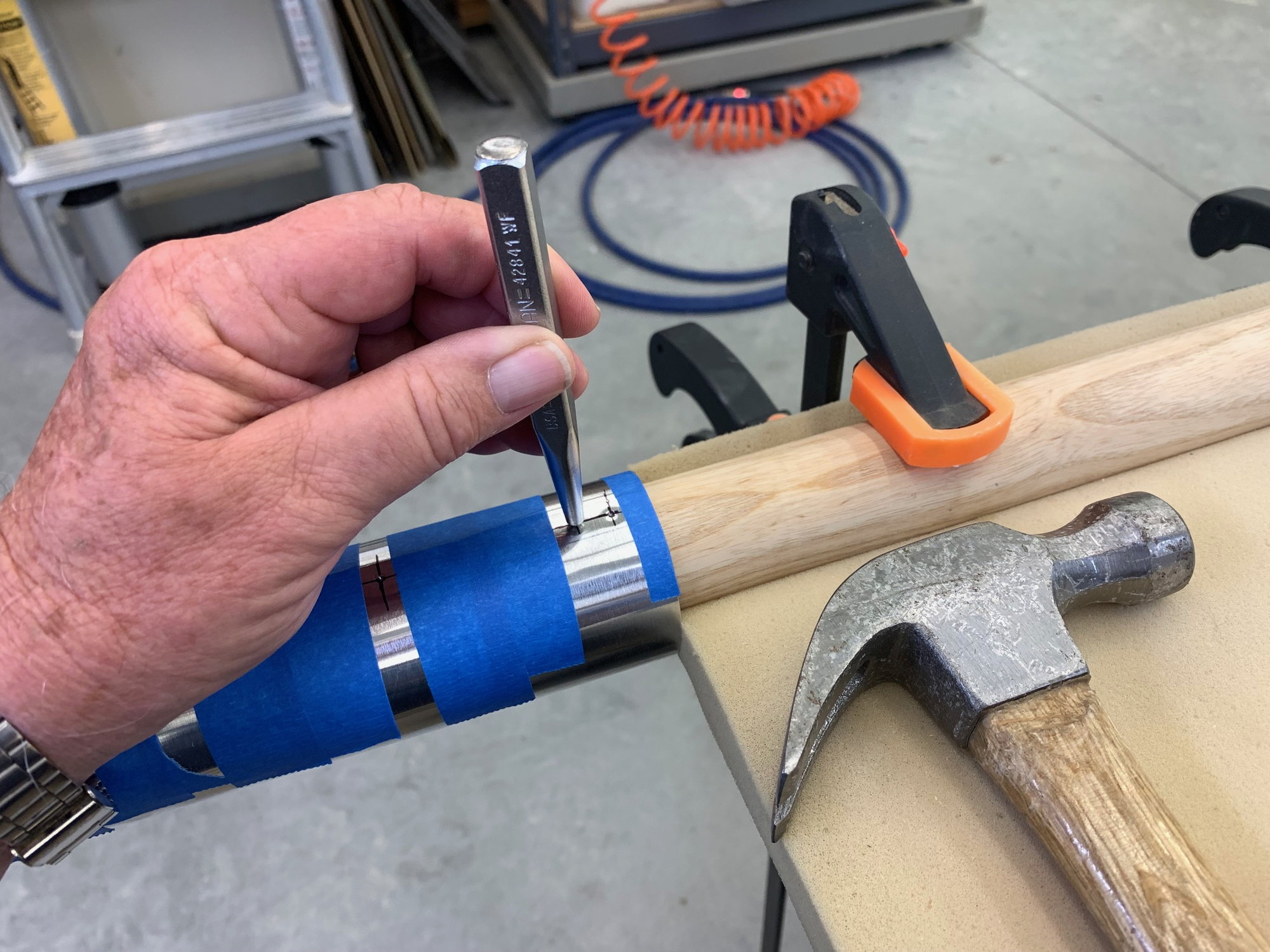
Holes punched
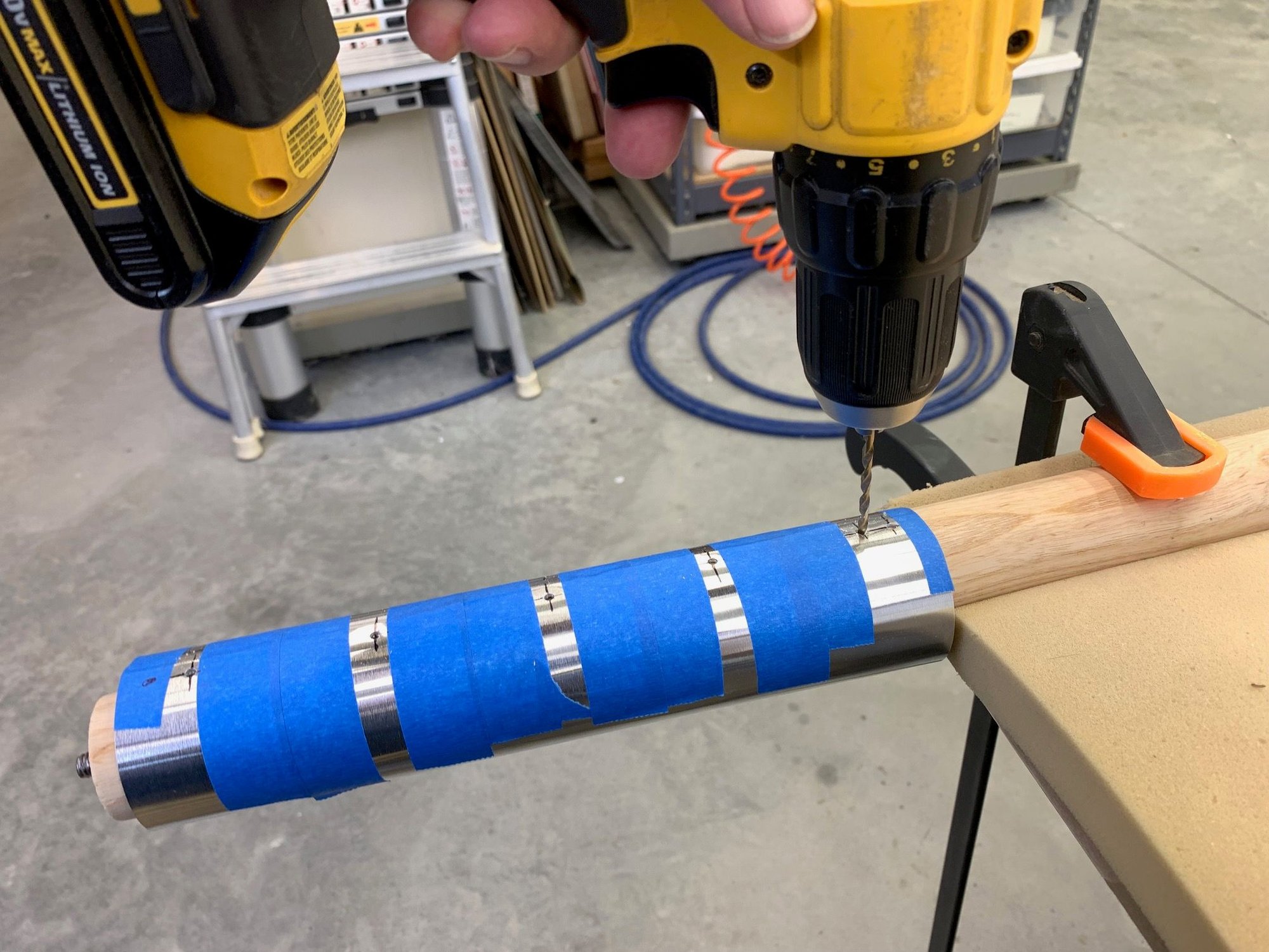
Drilled for 1/8" rivets
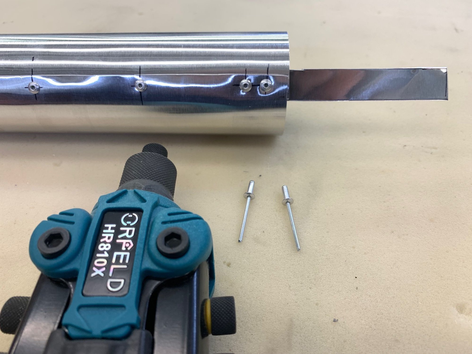
Pipe fastened with rivets
RIvets installed for standoffs from inner pipe
The rivets are ground down to 4mm inside the outer pipe to act as standoff from inner pipe
Finished double walled pipe
Plywood standoffs installed on foam
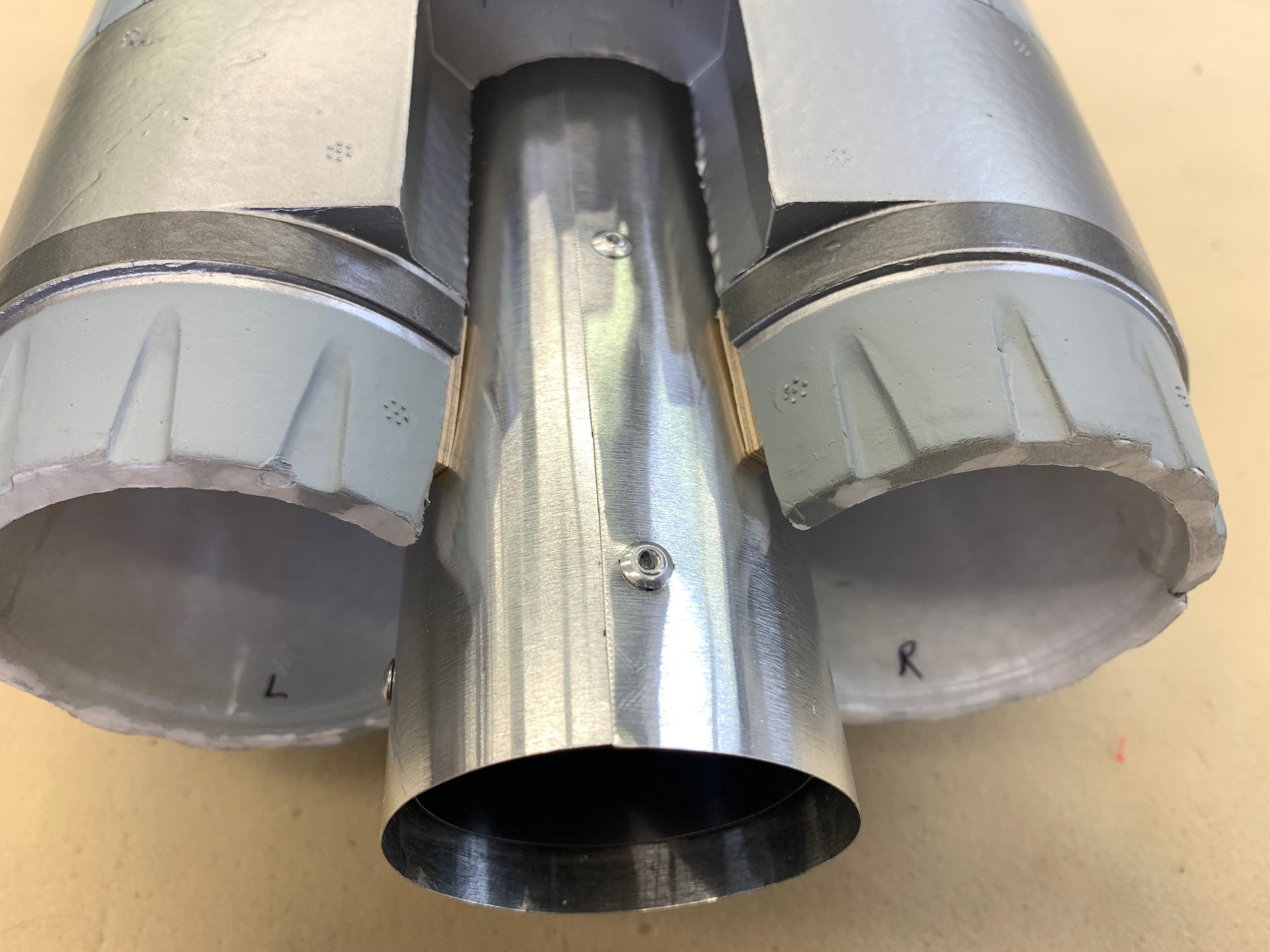
Good fit

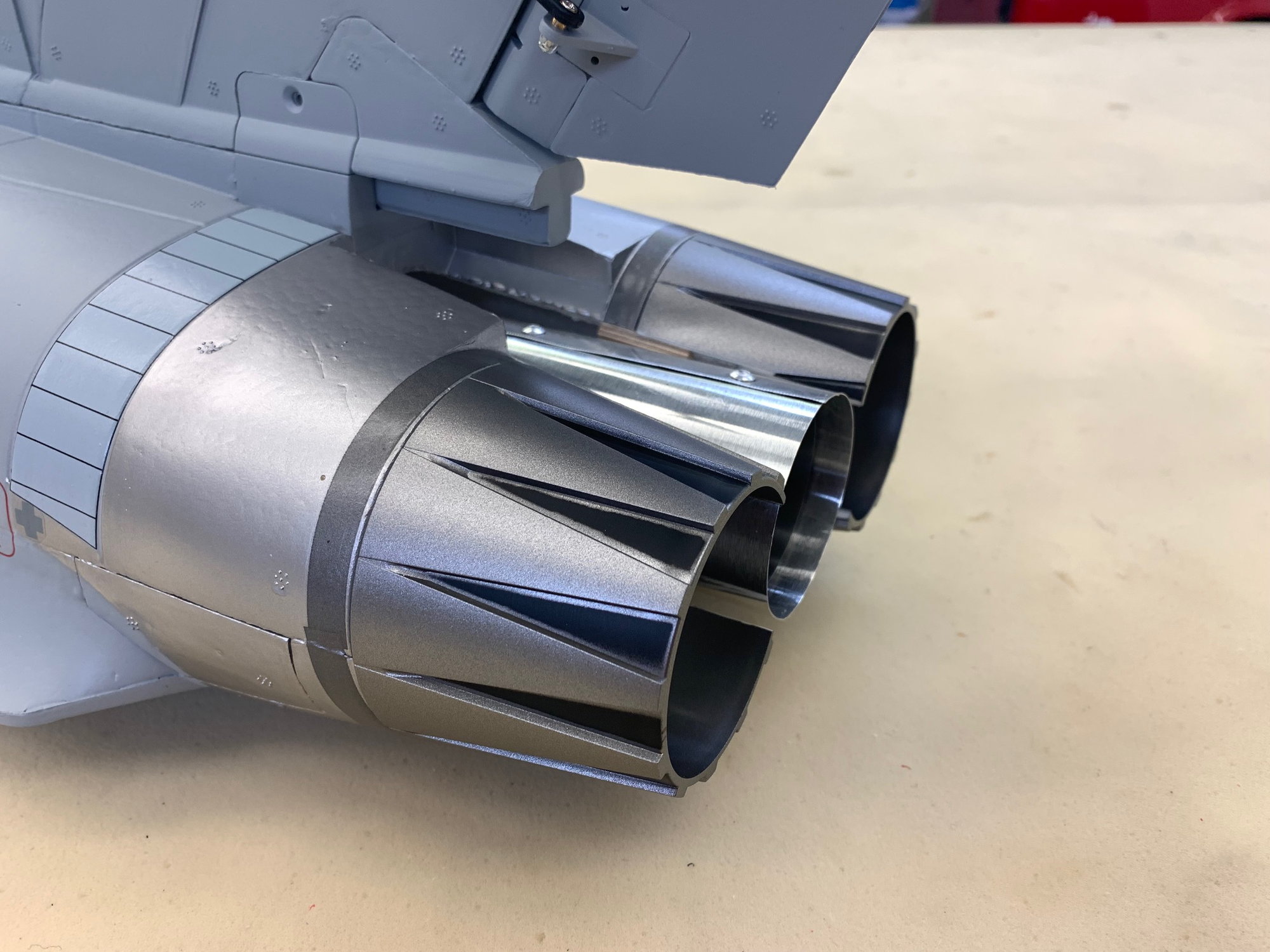
Looks like a Eurosport now. With the tail plug, and paint on the outer pipe it will blend in very well
I had the luxury of having the inner pipe already made by Keith. All I had to do was make the outer pipe.
The inner pipe and 3D cones are 46mm. The outer pipe is 54mm. With shims in the tail the rear hole in the cutting template was 58mm. For more detailed info on how I make the pipes see here:
Turbine Conversion Of 80mm Freewing A-10 To Single X-45 Turbine Post # 4-7
Cooking the HTPLA cones at 200 degrees for one hour
Cutting the outer pipe from roofing aluminum
Outer pipe rolled, taped, and marked
Holes punched
Drilled for 1/8" rivets
Pipe fastened with rivets
RIvets installed for standoffs from inner pipe
The rivets are ground down to 4mm inside the outer pipe to act as standoff from inner pipe
Finished double walled pipe
Plywood standoffs installed on foam
Good fit
Looks like a Eurosport now. With the tail plug, and paint on the outer pipe it will blend in very well
Last edited by Viper1GJ; 04-25-2023 at 06:08 PM.
The following 3 users liked this post by Viper1GJ:
The following users liked this post:
Viper1GJ (04-26-2023)
The following users liked this post:
Viper1GJ (04-26-2023)
04-26-2023, 05:18 PM
#16
Thread Starter
My Feedback: (20)
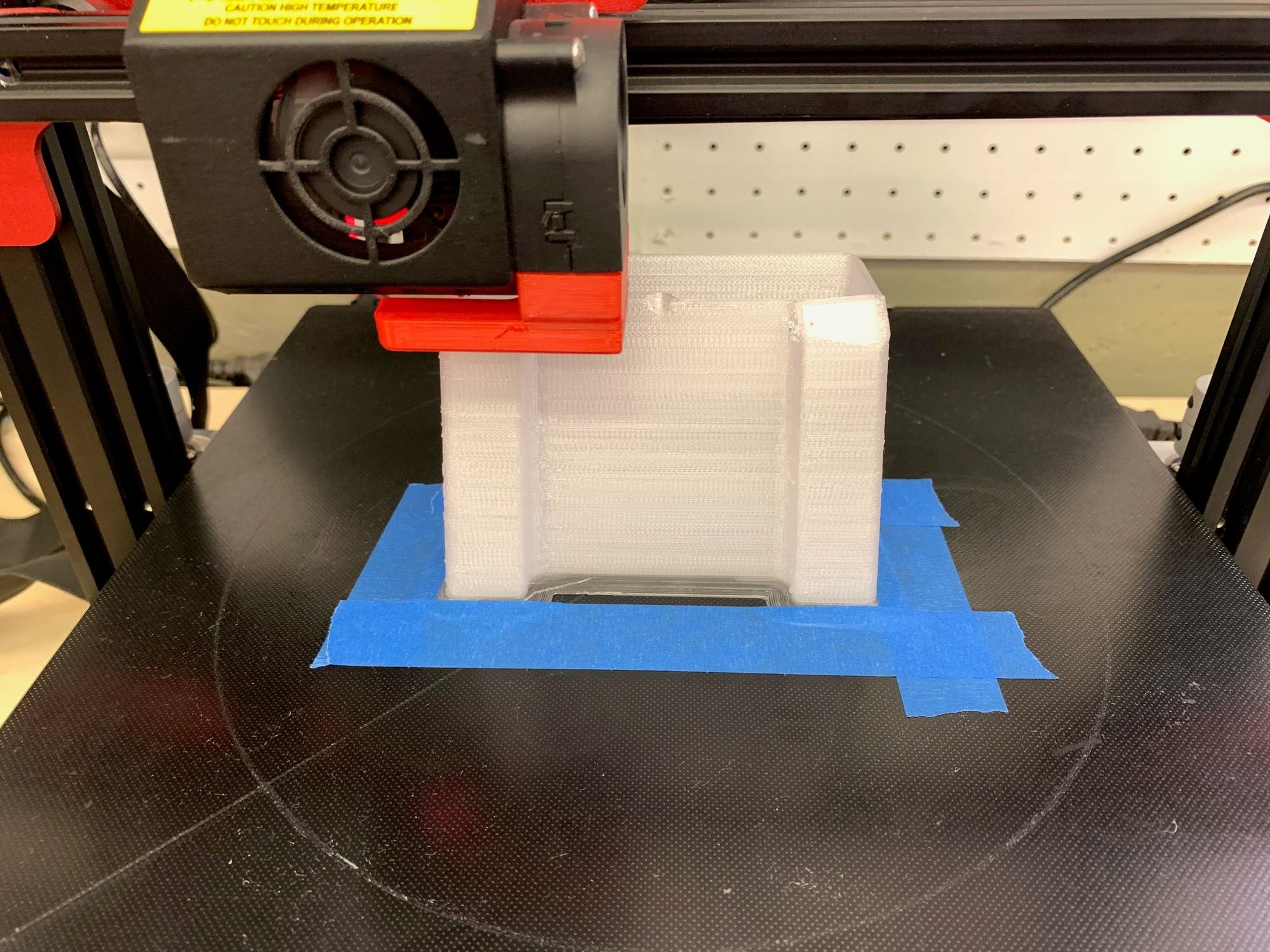
Spent most of shop time today fussing with 3D printer settings. I'm still a novice at it. Trying to print the latest version of tanks that Keith sent me with mods for pick up tube. This one was completed but has some flaws. Will do another one later.
04-27-2023, 03:00 PM
#17
Thread Starter
My Feedback: (20)
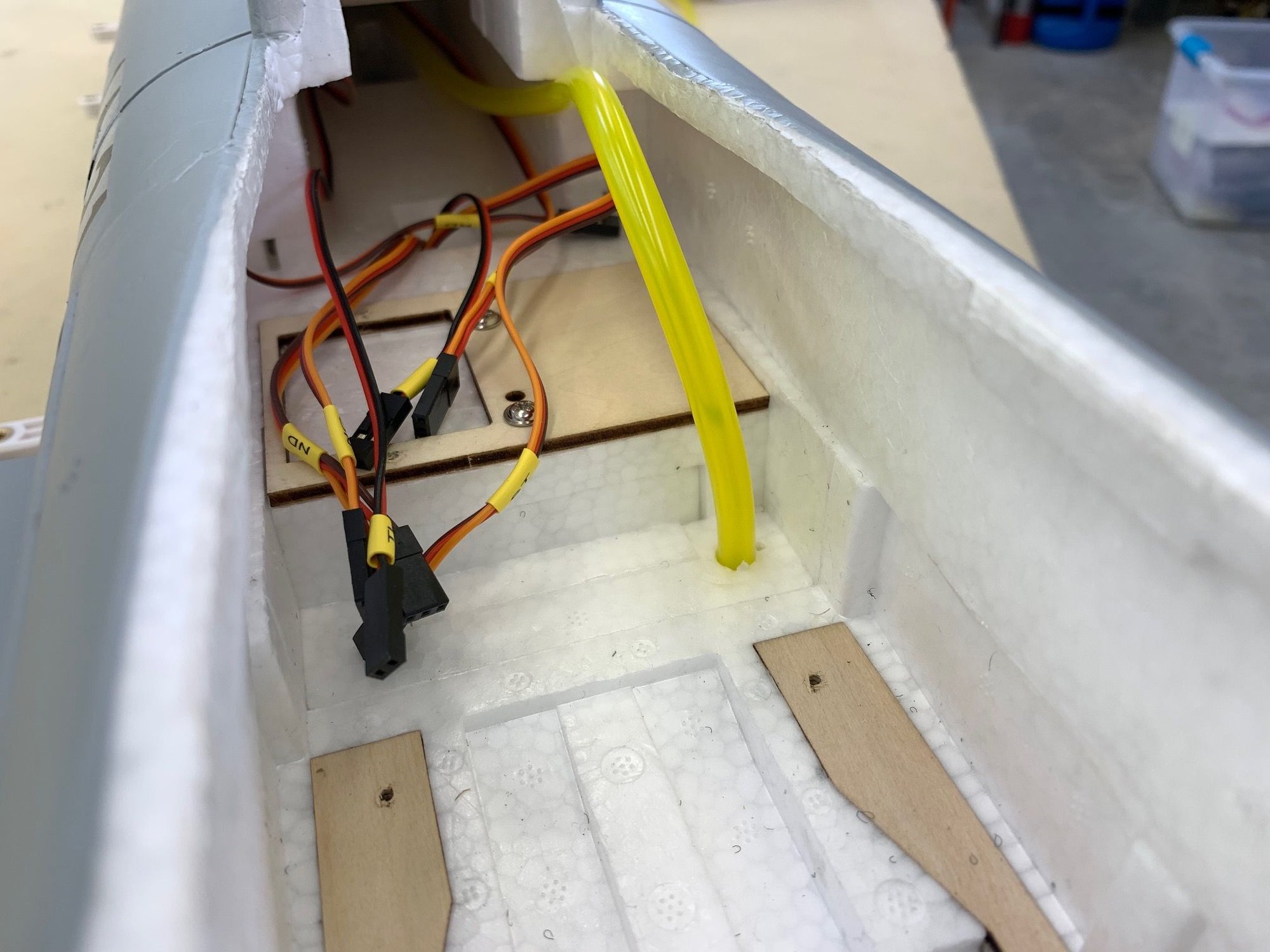
I plan on having all flight controls plugged directly into the receiver and bypass the Freewing mixing board. This will allow me independent control of each flight control for adjustments and mixing in the Jeti radio. I want to keep the easy plug ribbon cable for the gear and lights so I had to separate the elevon servo signals from the ribbon cable.

I found this ribbon cable mapping on RCG posted by Kallend. I can confirm the elevon is as shown.
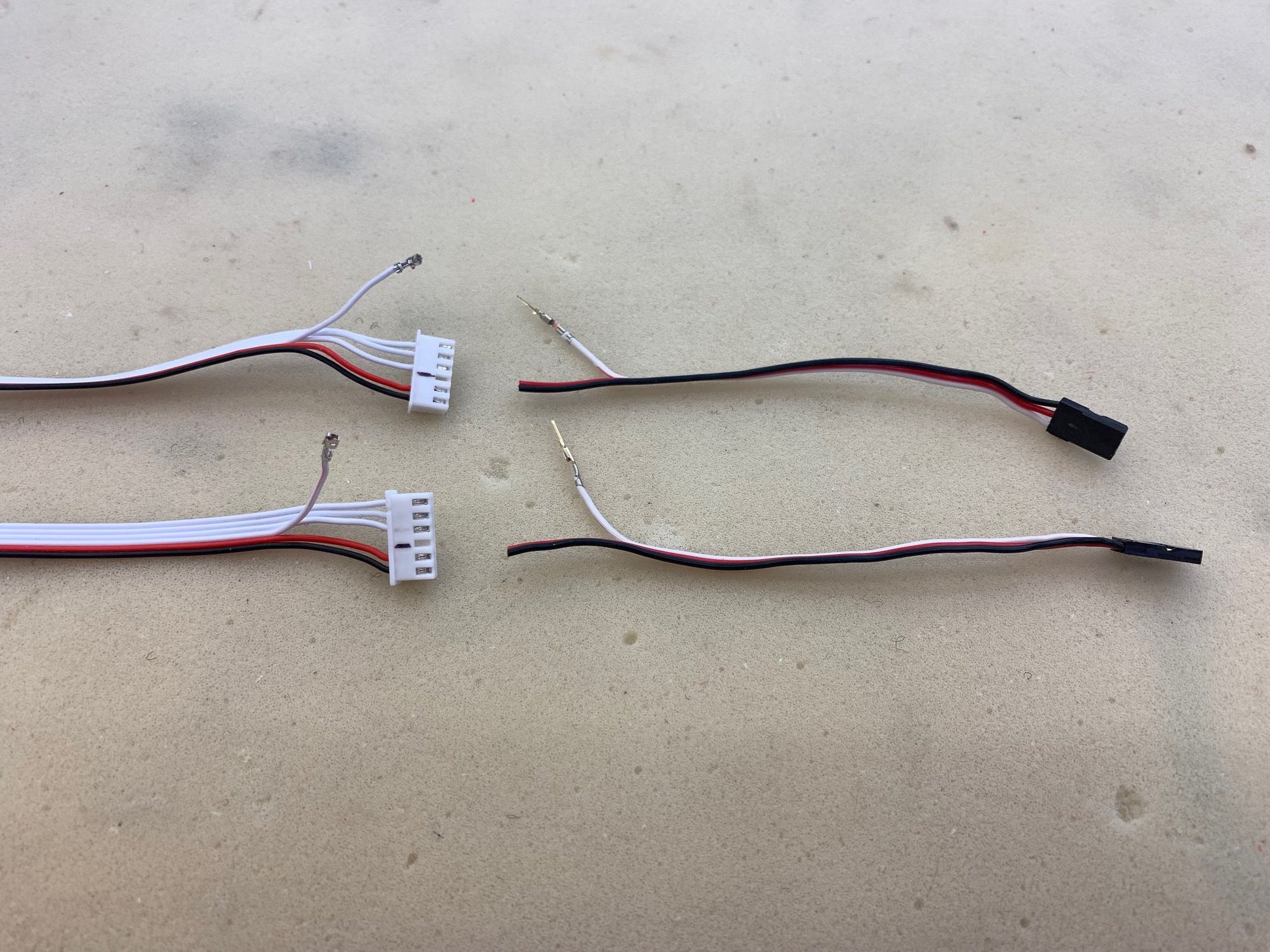
I pushed the female connector out of the ribbon cable connector using a vice to hold plug and a #2 Xacto blade to push the locking tab in. I crimped a male pin on the signal wire from two male servo wires.
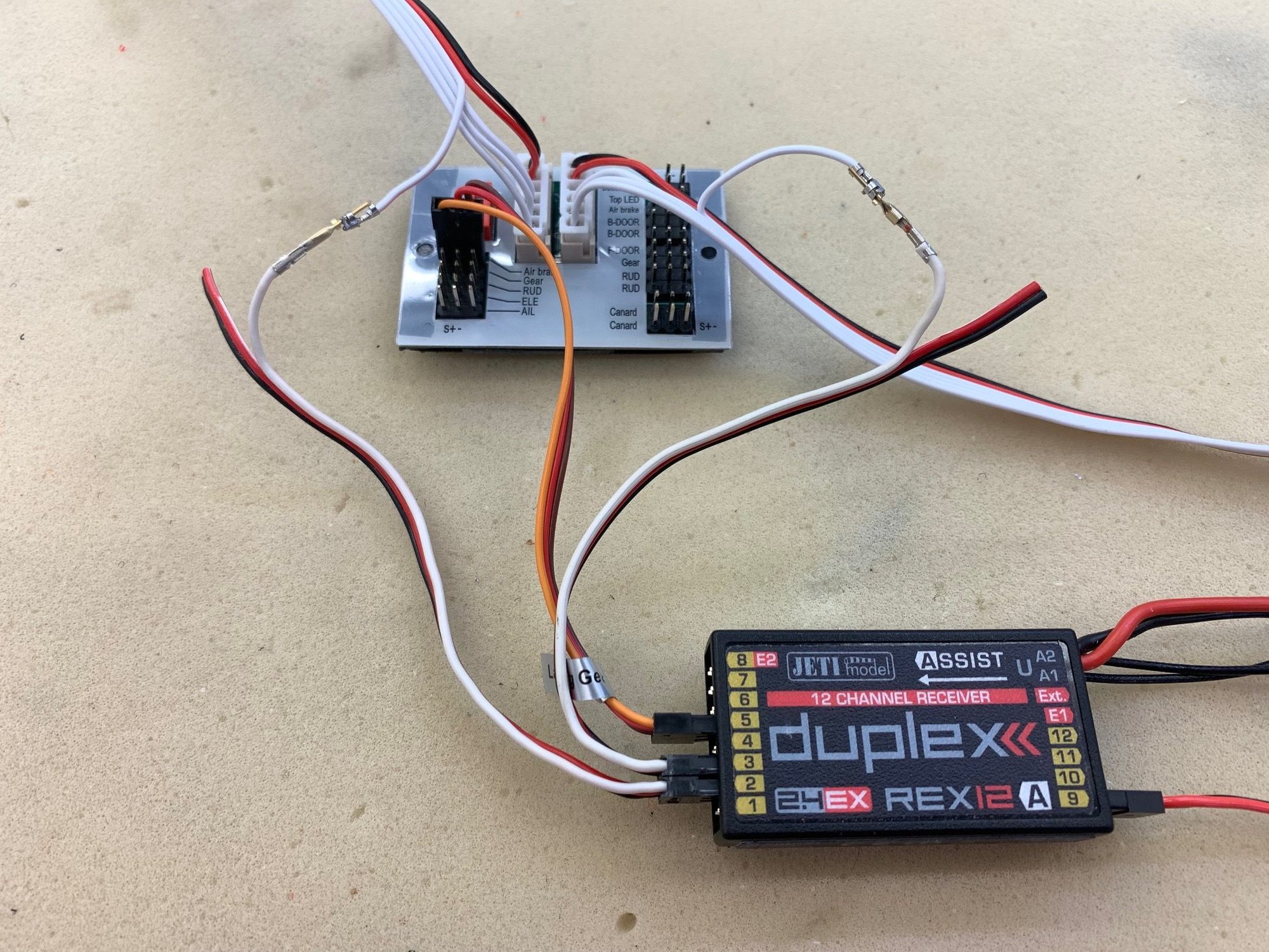
Elevon servo testing hook up. Power to the board is supplied by the jumper in the gear channel
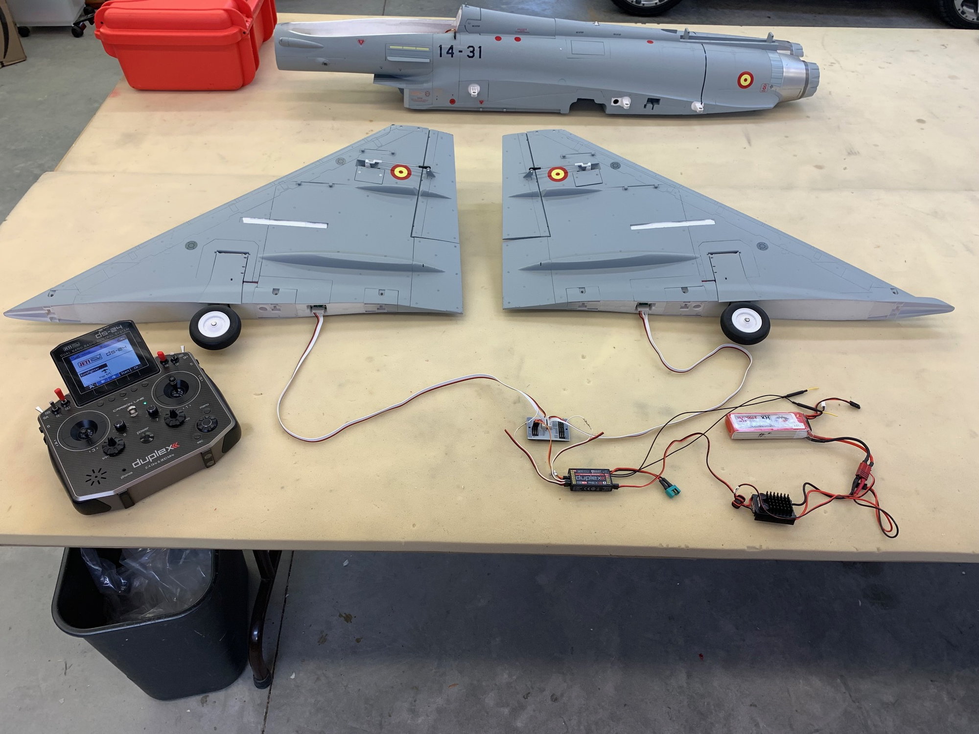
WIngs, BEC, and battery connected. Elevon servos worked correctly.
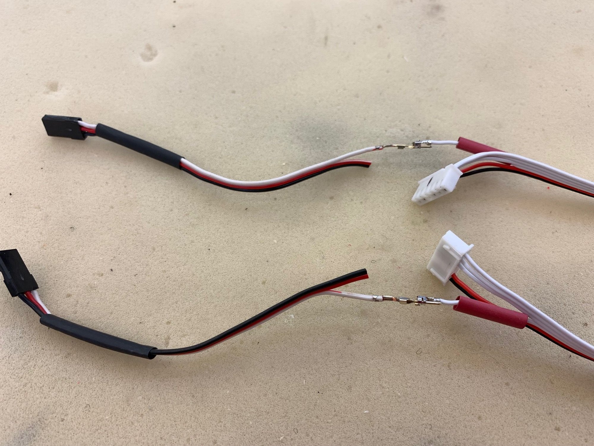
Heat shrink tubing applied to wires and connectors connected.
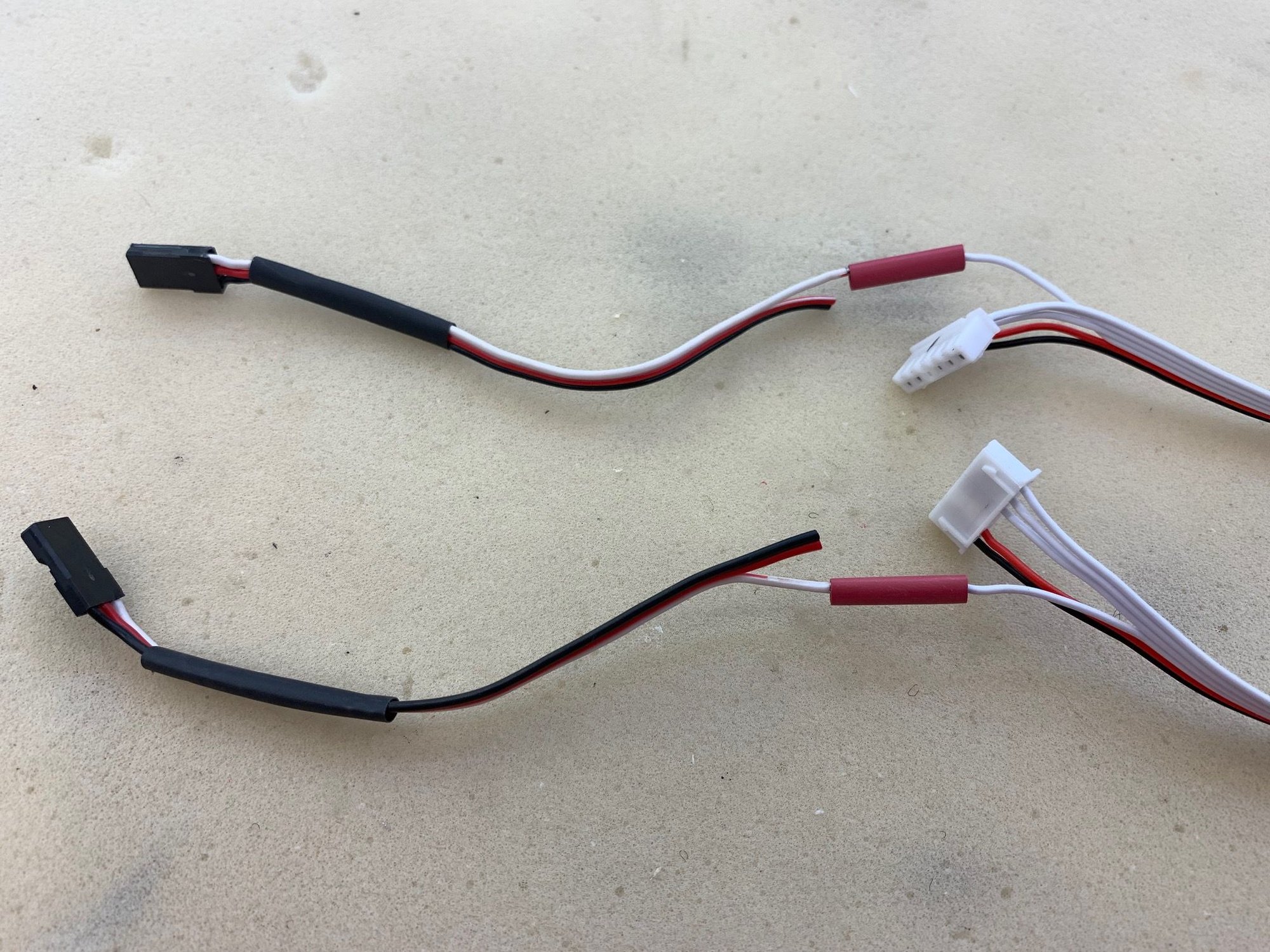
Heat shrink pushed over connectors.
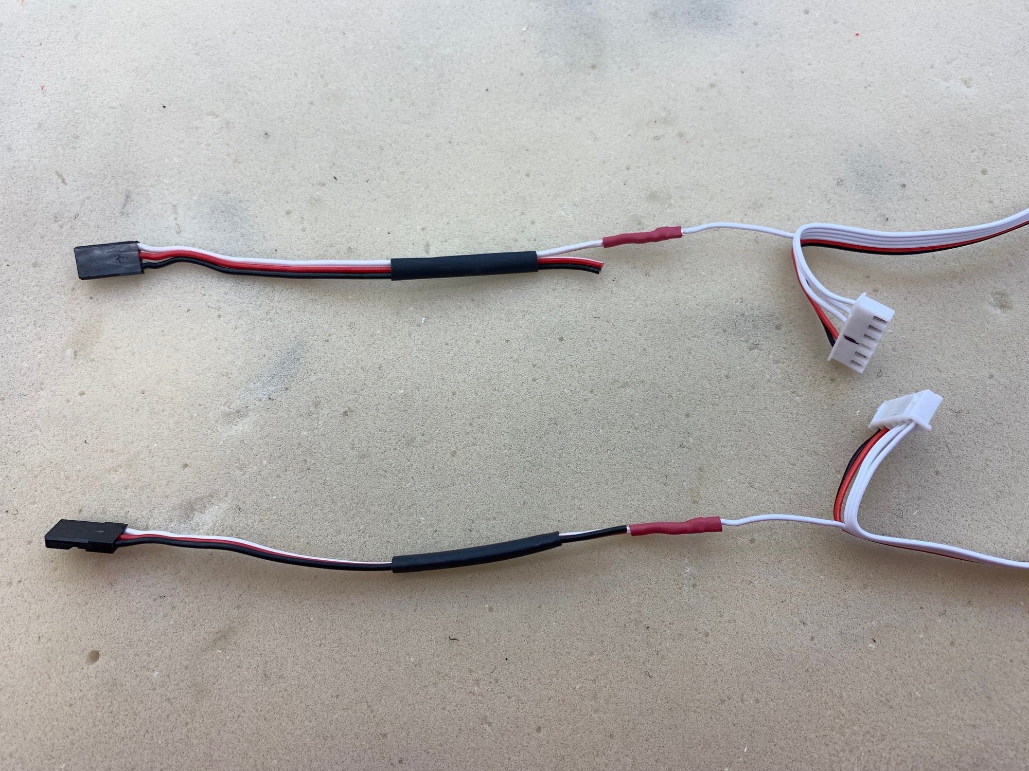
Red tubing shrunk tight over connectors.
Black tubing over the connection to keep the red and black wires secured and overlap the connection.
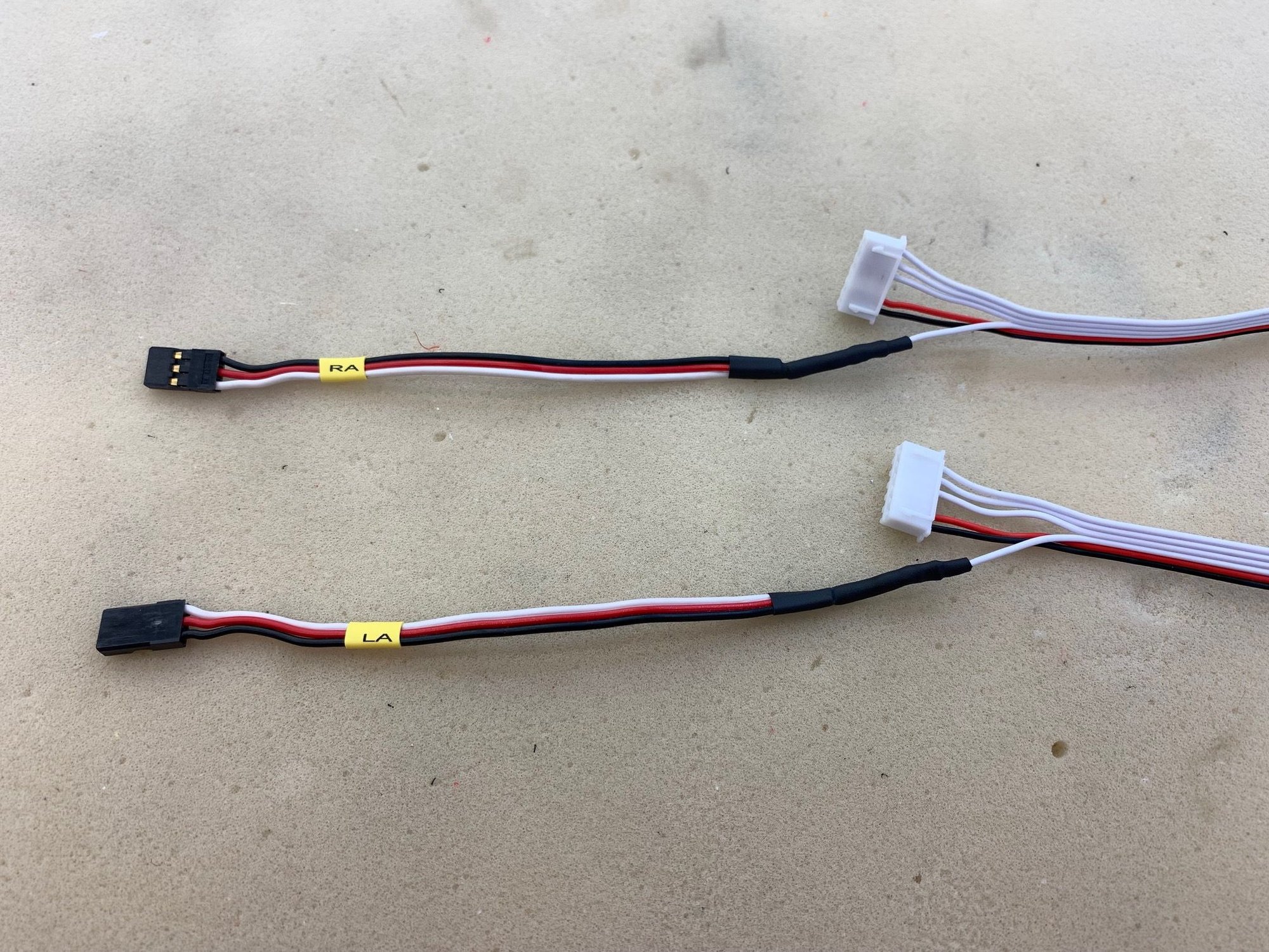
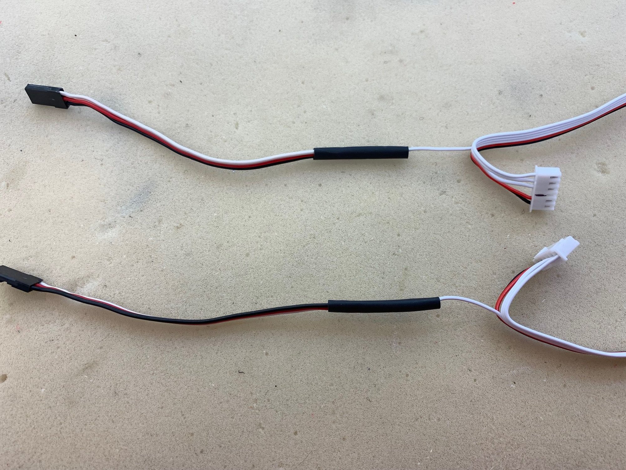
All tubing and labels heat shrunk tight. The red and black wires are not used electrically but are only for additional mechanical friction to secure the plug to the receiver pins.

All cables are now labeled.
I've read that the gear cycle time being excessively long so I will hook up all the door and gear servos and test. If necessary I can operate the gear and doors from the Jeti radio sequencer.
I found this ribbon cable mapping on RCG posted by Kallend. I can confirm the elevon is as shown.
I pushed the female connector out of the ribbon cable connector using a vice to hold plug and a #2 Xacto blade to push the locking tab in. I crimped a male pin on the signal wire from two male servo wires.
Elevon servo testing hook up. Power to the board is supplied by the jumper in the gear channel
WIngs, BEC, and battery connected. Elevon servos worked correctly.
Heat shrink tubing applied to wires and connectors connected.
Heat shrink pushed over connectors.
Red tubing shrunk tight over connectors.
Black tubing over the connection to keep the red and black wires secured and overlap the connection.
All tubing and labels heat shrunk tight. The red and black wires are not used electrically but are only for additional mechanical friction to secure the plug to the receiver pins.
All cables are now labeled.
I've read that the gear cycle time being excessively long so I will hook up all the door and gear servos and test. If necessary I can operate the gear and doors from the Jeti radio sequencer.
04-29-2023, 02:44 PM
#18
Thread Starter
My Feedback: (20)
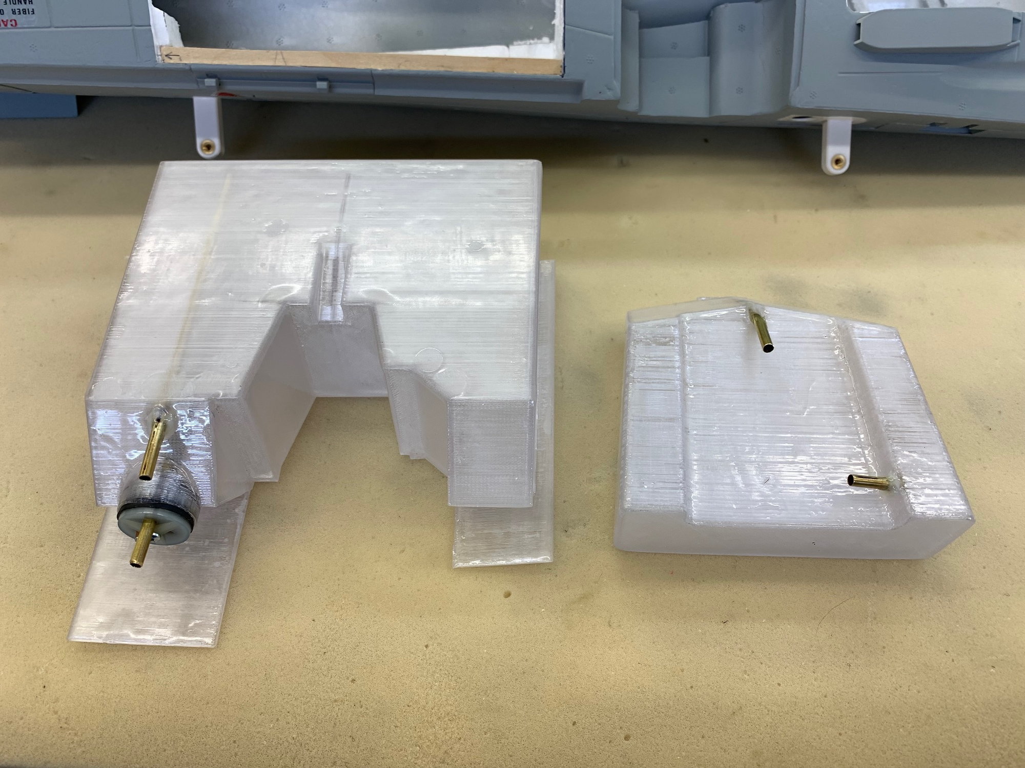
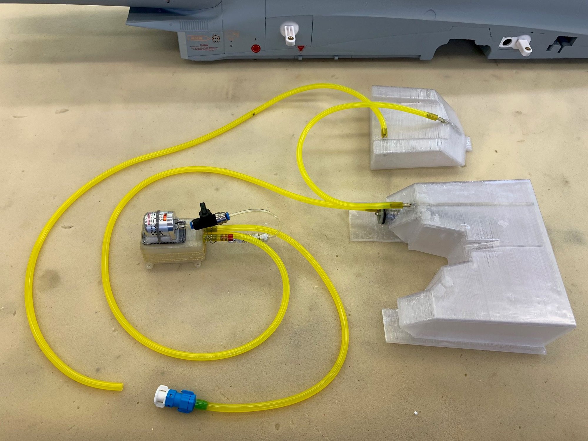
Fuel tank plumbing fabricated and dry fit
Finally got the tanks off the 3D printer and fabricated parts for plumbing. The hardest part was figuring out where to put tubing so the tanks could all be removed still connected for maintenance if needed.
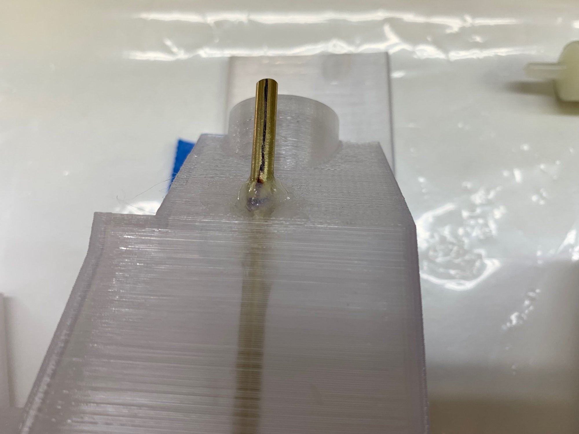
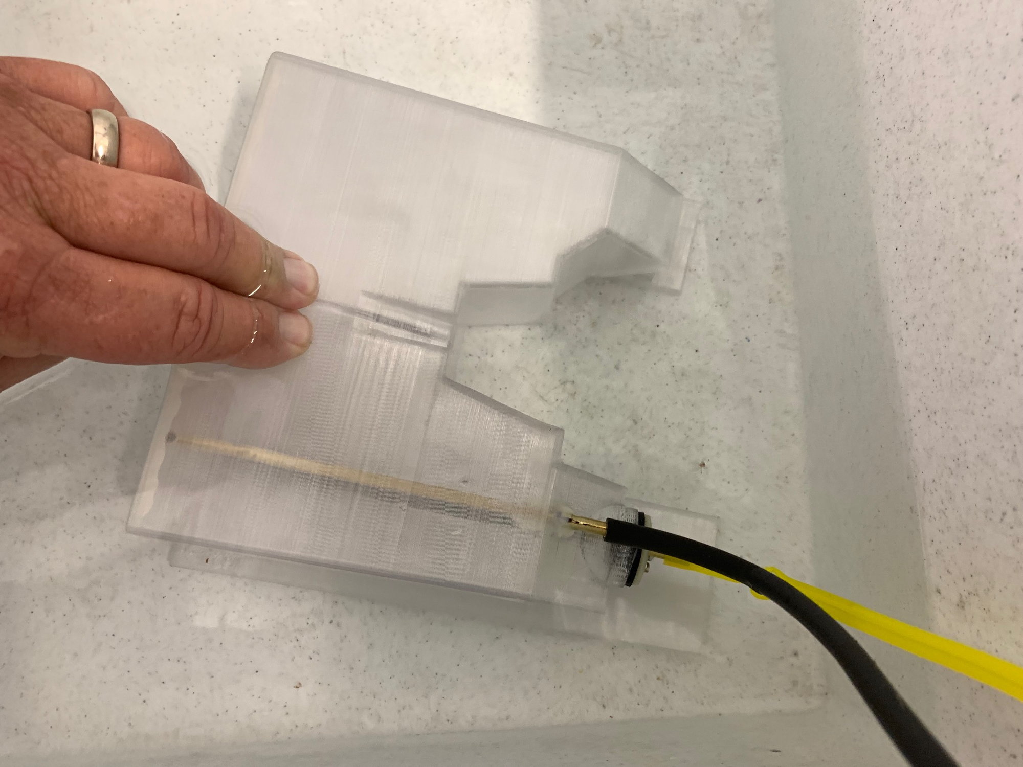
The main tank vent tube goes to the back of the tank. A winged felt clunk is attached with Viton tubing to the stopper outlet. The second tube in the stopper is plugged with silver solder.
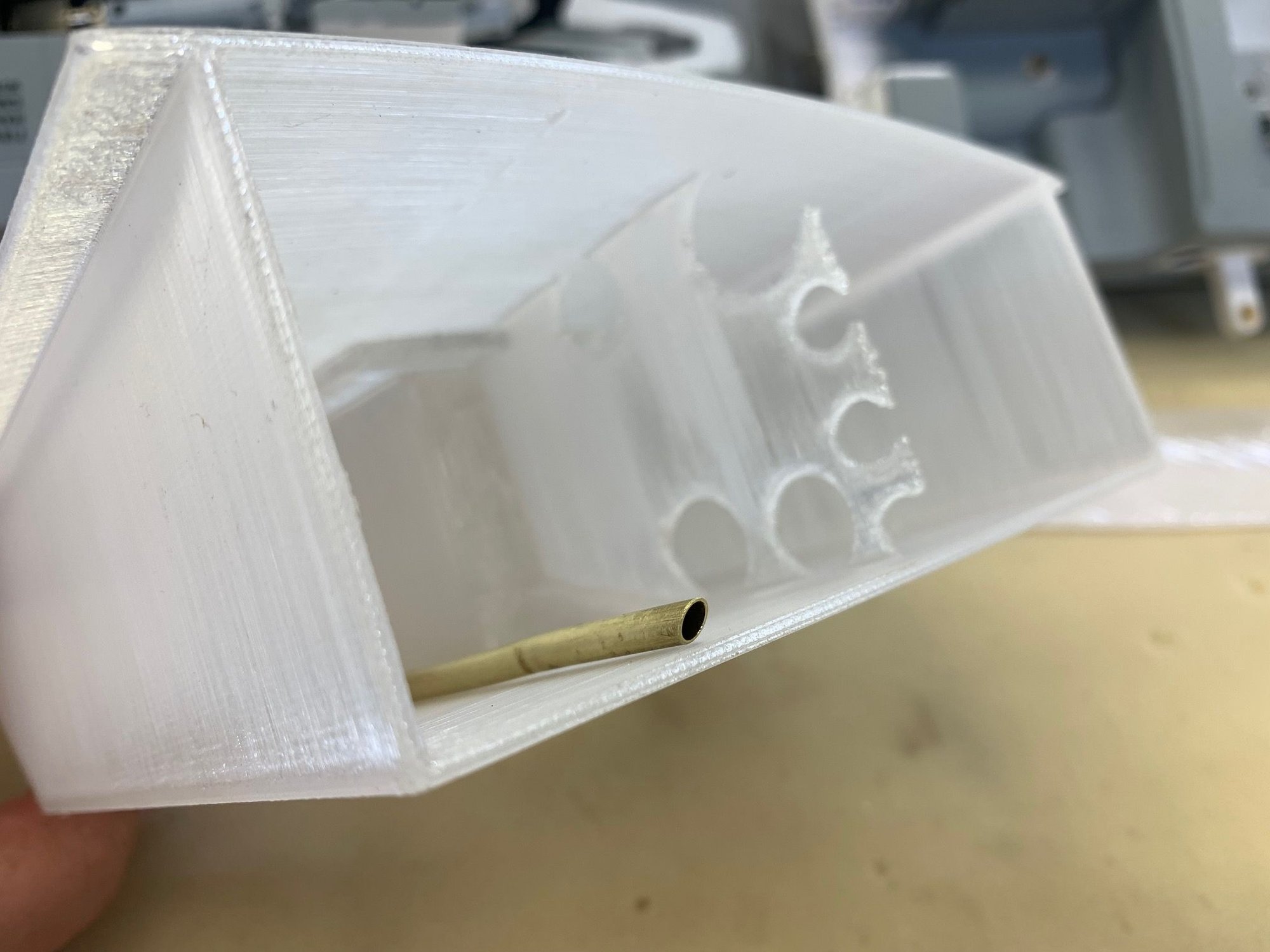
Closeup of main tank vent at rear of tank. The baffle is mainly for a 3D printing support for the center of the tank but will reduce side to side sloshing also.
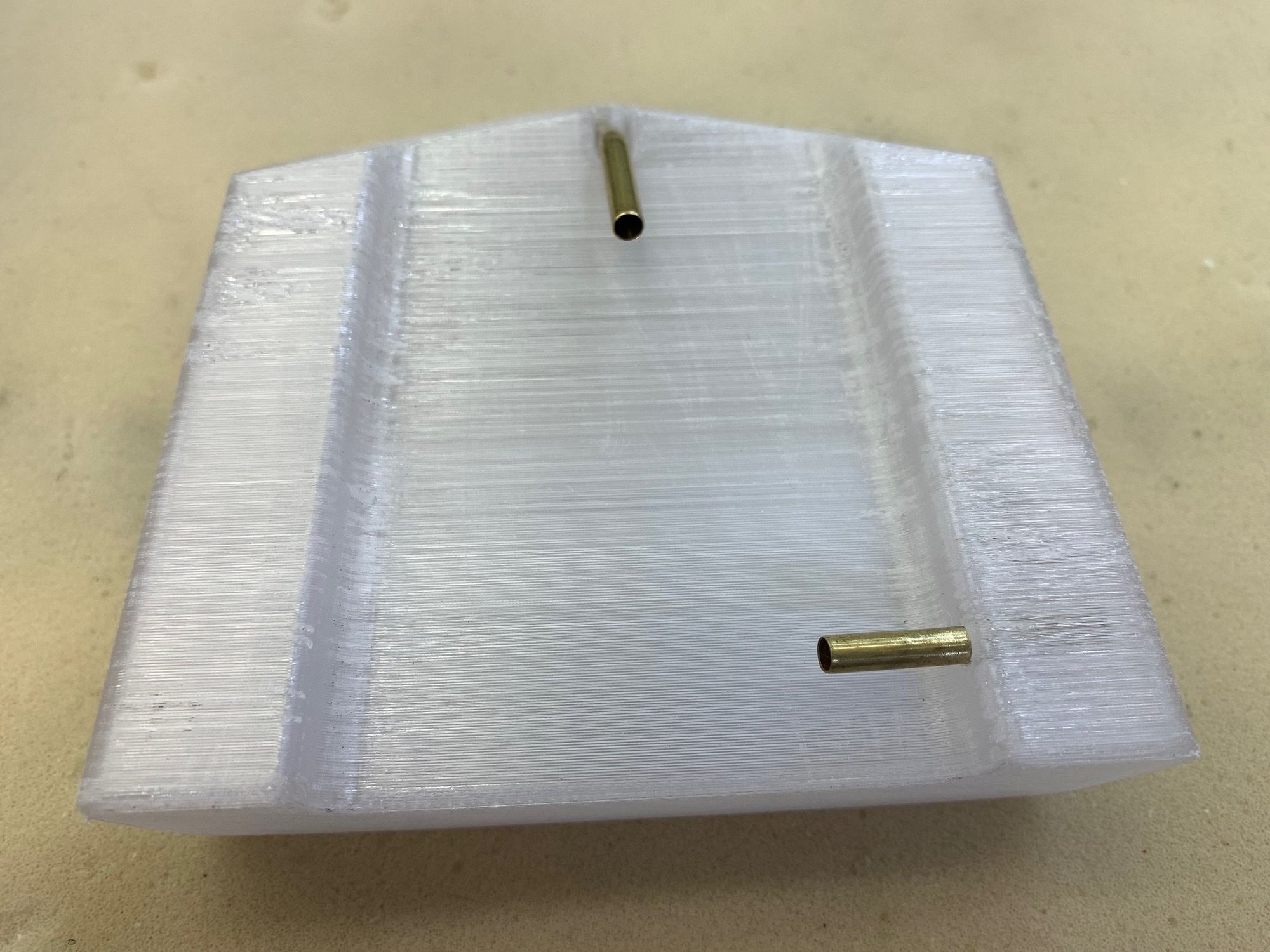
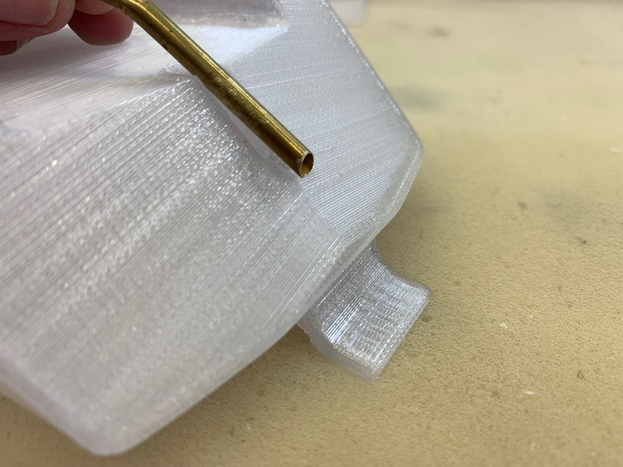
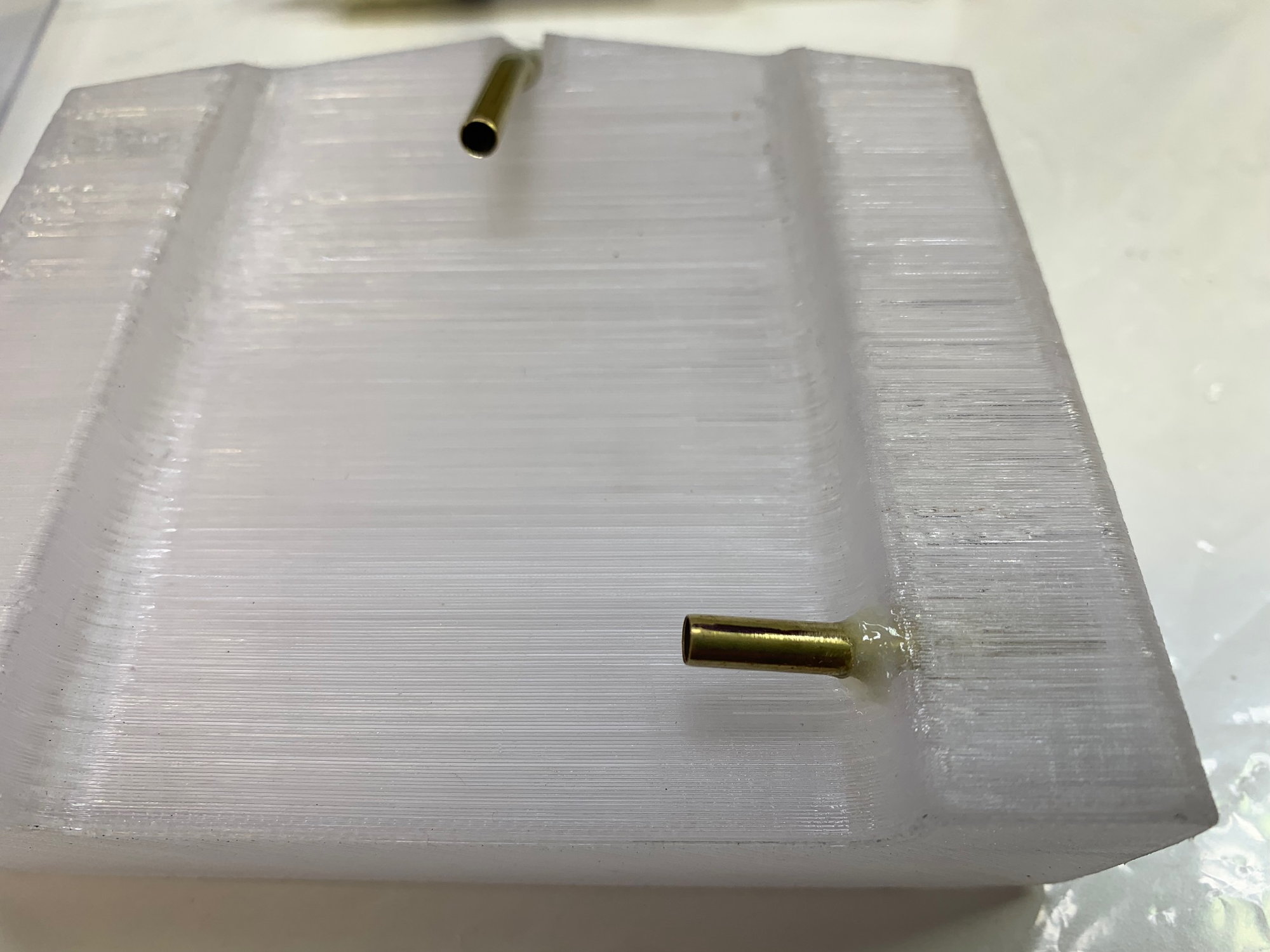
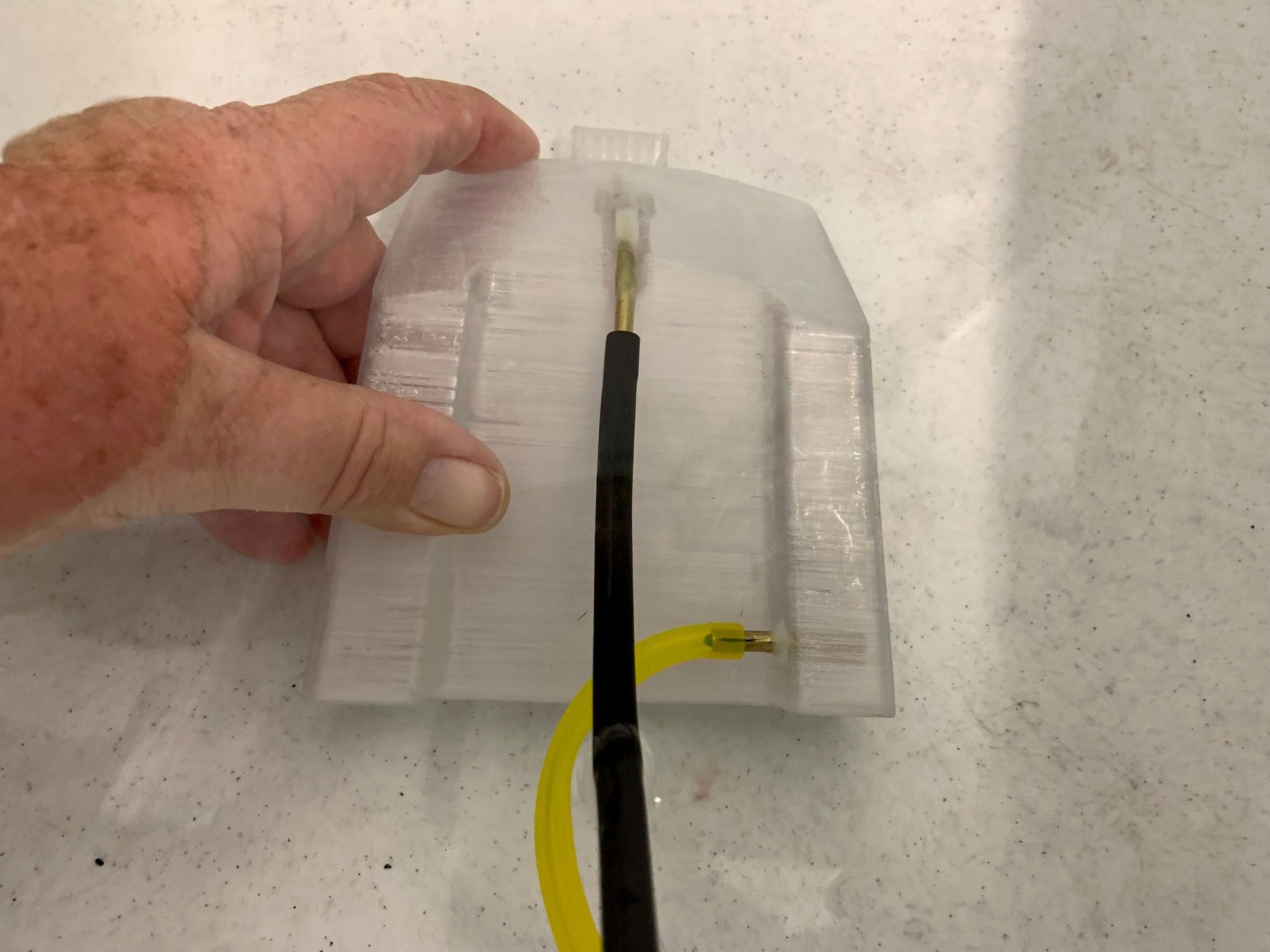
Aft aux tank has a fixed rear pickup tube and side mounted vent tube. The pickup tube feeds into the man tank vent tube. The vent tube will go up and forward above the air trap tank in the cockpit area since the air trap tank is higher than both fuel tanks. Then it will exit out the bottom of the forward fuse.
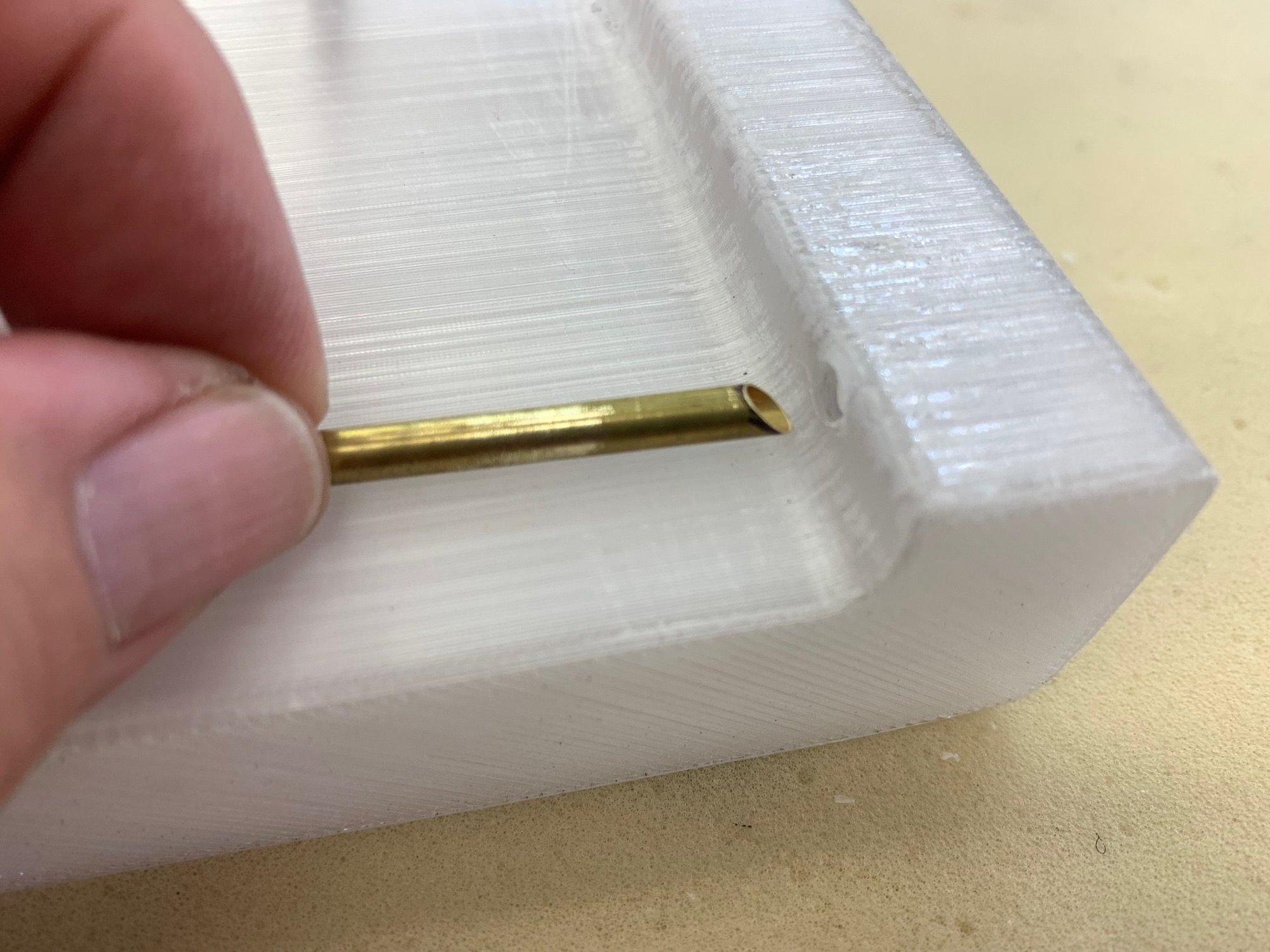
Beveled end of aux tank vent tube
Beveled end of aux tank pickup tube will be placed just off the bottom of the tank. The shape of the tank will funnel residual fuel to the back end where the pickup tube is. There is no need for a clunk in the aux tank since the main tank has 4 times the volume and can trap any air if it gets sucked in before the aux tank empties. Epoxy coating inside and outside of tanks next.
Finally got the tanks off the 3D printer and fabricated parts for plumbing. The hardest part was figuring out where to put tubing so the tanks could all be removed still connected for maintenance if needed.
The main tank vent tube goes to the back of the tank. A winged felt clunk is attached with Viton tubing to the stopper outlet. The second tube in the stopper is plugged with silver solder.
Closeup of main tank vent at rear of tank. The baffle is mainly for a 3D printing support for the center of the tank but will reduce side to side sloshing also.
Aft aux tank has a fixed rear pickup tube and side mounted vent tube. The pickup tube feeds into the man tank vent tube. The vent tube will go up and forward above the air trap tank in the cockpit area since the air trap tank is higher than both fuel tanks. Then it will exit out the bottom of the forward fuse.
Beveled end of aux tank vent tube
Beveled end of aux tank pickup tube will be placed just off the bottom of the tank. The shape of the tank will funnel residual fuel to the back end where the pickup tube is. There is no need for a clunk in the aux tank since the main tank has 4 times the volume and can trap any air if it gets sucked in before the aux tank empties. Epoxy coating inside and outside of tanks next.
The following users liked this post:
Viper1GJ (04-30-2023)
04-30-2023, 04:02 PM
#20
Thread Starter
My Feedback: (20)
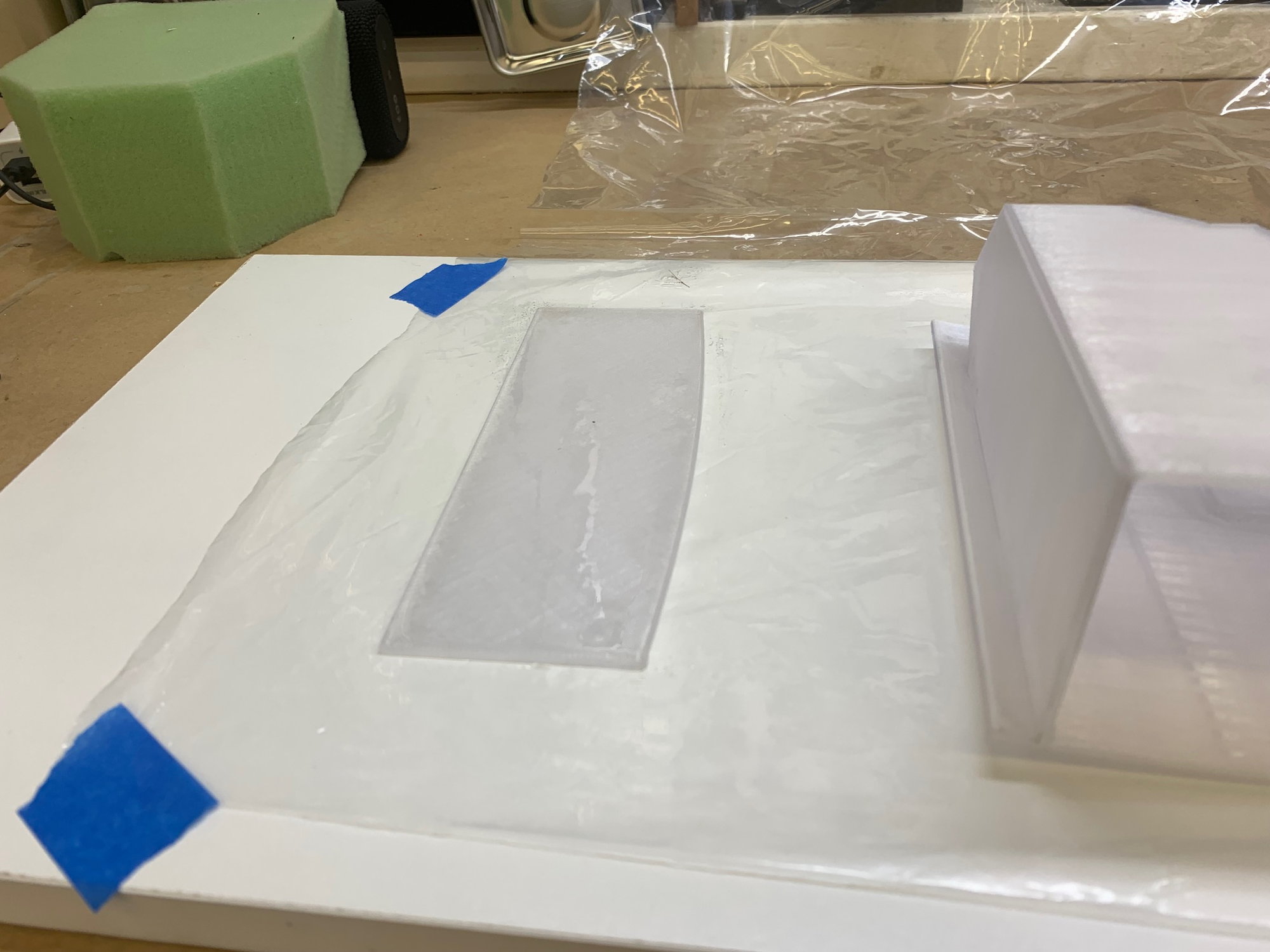
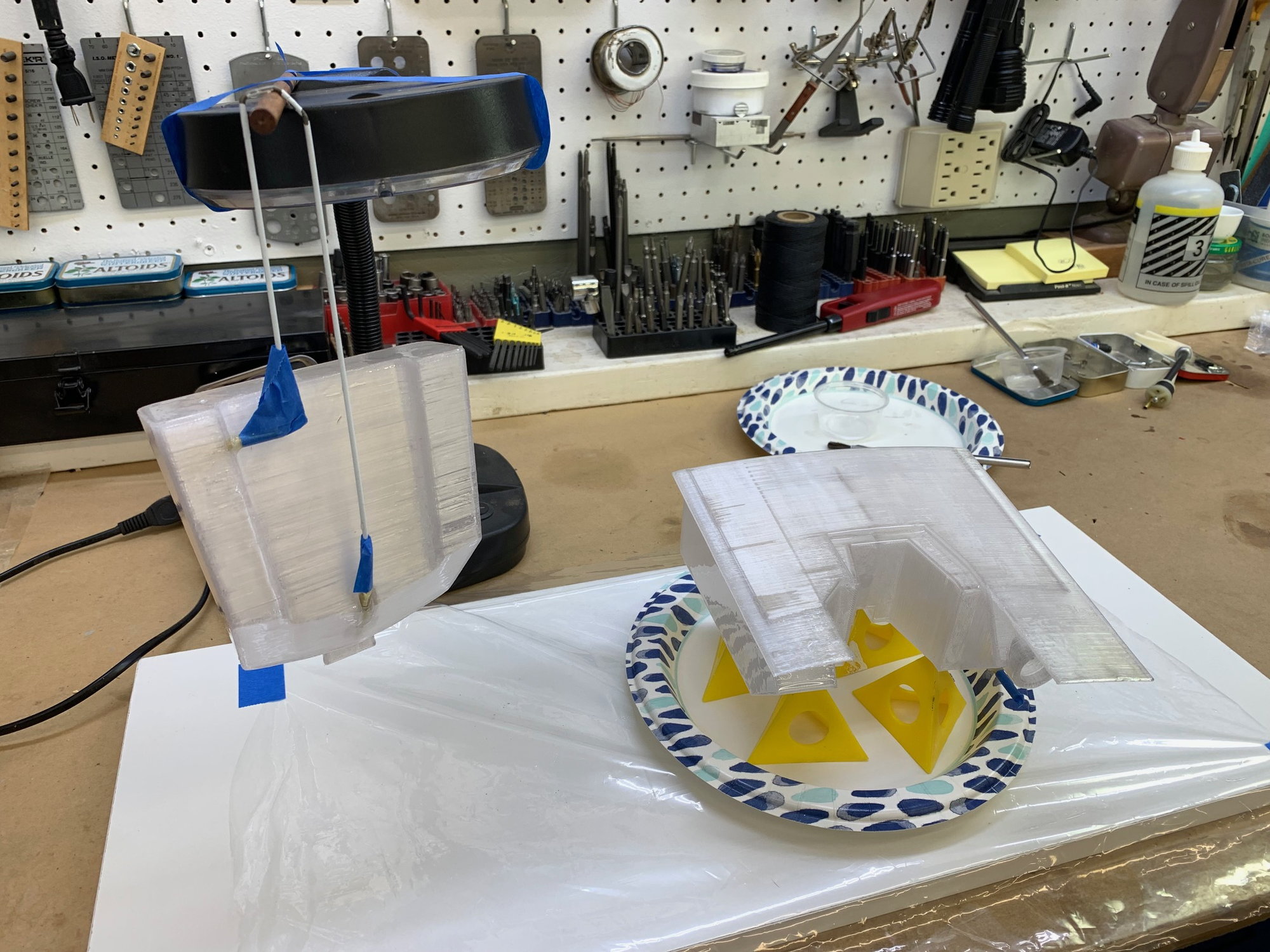
Fuel Tanks epoxy coated on the inside and assembled.

MAS LV laminating epoxy mixed 1 to .46 by weight used to coat the inside of the tanks.

Approximately 20 grams of epoxy was injected inside the aux tank through the vent hole. The tank was then rotated around to spread the epoxy on all inside surfaces. Excess epoxy was drained out the vent hole and the tank propped up level for cure.
Inside surface of front tank back plate coated with small brush.
Inside of main tank coated with a small brush.
Insides coated and curing.
After inside was cured the aux tank tubes were epoxied in place using Total Boat Thixo thickened epoxy.
Front tank vent tube tacked in place with CA and then installed with thickened epoxy on inside and outside of the joint

Main tank back plate installed. A bead of epoxy was laid onto the edge both parts using a syringe prior to assembly This made a good corner fillet inside when the back was pressed in place. The excess squeeze out was wiped off the outside. I made sure there was no epoxy stuck in the vent tube.
Parts assembled and curing. Outside epoxy coating next.
MAS LV laminating epoxy mixed 1 to .46 by weight used to coat the inside of the tanks.
Approximately 20 grams of epoxy was injected inside the aux tank through the vent hole. The tank was then rotated around to spread the epoxy on all inside surfaces. Excess epoxy was drained out the vent hole and the tank propped up level for cure.
Inside surface of front tank back plate coated with small brush.
Inside of main tank coated with a small brush.
Insides coated and curing.
After inside was cured the aux tank tubes were epoxied in place using Total Boat Thixo thickened epoxy.
Front tank vent tube tacked in place with CA and then installed with thickened epoxy on inside and outside of the joint
Main tank back plate installed. A bead of epoxy was laid onto the edge both parts using a syringe prior to assembly This made a good corner fillet inside when the back was pressed in place. The excess squeeze out was wiped off the outside. I made sure there was no epoxy stuck in the vent tube.
Parts assembled and curing. Outside epoxy coating next.
Last edited by Viper1GJ; 04-30-2023 at 04:07 PM.
The following users liked this post:
jcterrettaz (05-02-2023)
05-02-2023, 02:38 PM
#21
Thread Starter
My Feedback: (20)
Callie Graphics Arrived
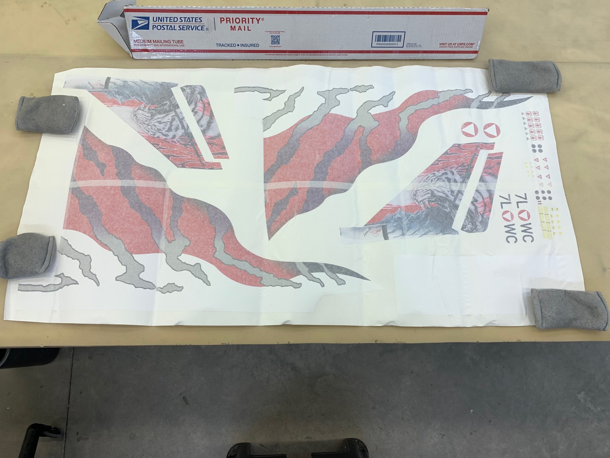
These Callie Graphics arrived to day. They are for the Austrian Tiger scheme. I will attempt to apply them to the jet only after test flying and proving the jet airworthy after the turbine conversion. I chose them because I'm lazy and wanted color contrast with out repainting the jet. The bottom is standard grey and the vinyl graphics only have to be applied to the top of the jet. I've never attempted this type of vinyl before so we will see how it goes.
Any application suggestions welcome!

Austrian Tiger scheme.
These Callie Graphics arrived to day. They are for the Austrian Tiger scheme. I will attempt to apply them to the jet only after test flying and proving the jet airworthy after the turbine conversion. I chose them because I'm lazy and wanted color contrast with out repainting the jet. The bottom is standard grey and the vinyl graphics only have to be applied to the top of the jet. I've never attempted this type of vinyl before so we will see how it goes.
Any application suggestions welcome!
Austrian Tiger scheme.
Last edited by Viper1GJ; 05-02-2023 at 02:54 PM.
05-02-2023, 02:52 PM
#22
Thread Starter
My Feedback: (20)
Tank Plumbing and Dry Fit
Tanks coated on outside with laminating epoxy.

WInged felt clunk installed viewed from bottom.
Clunk from side view.
Aux tank leak tested under water by blowing air into both tubes. No leaks detected.
Main tank tested with no leaks detected.
Tanks finished and ready to install
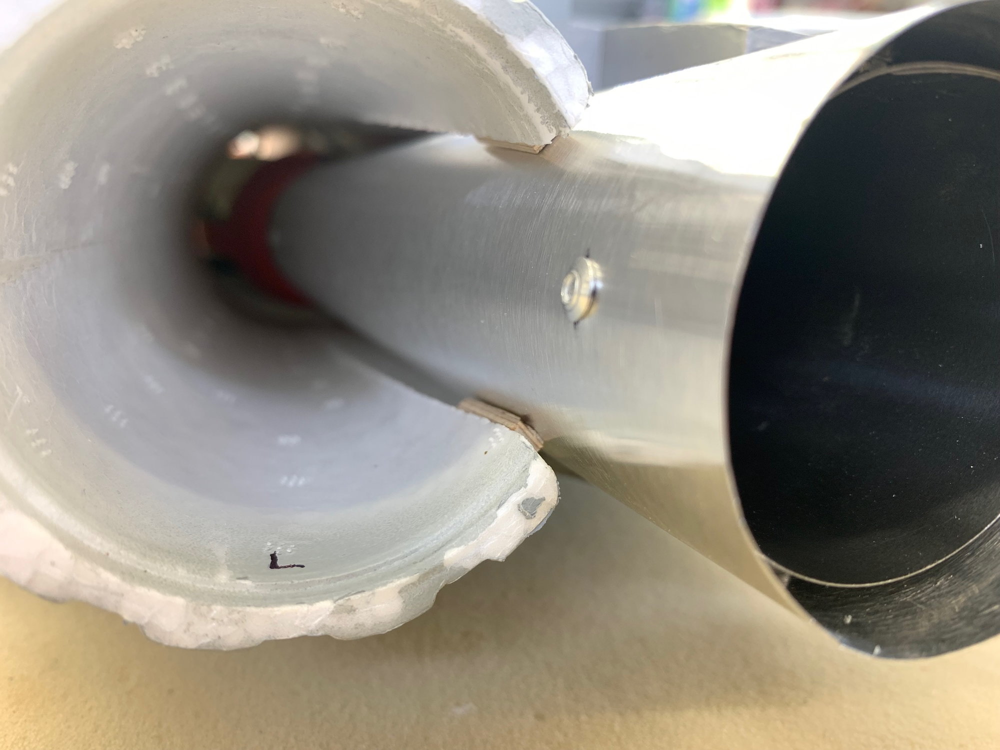
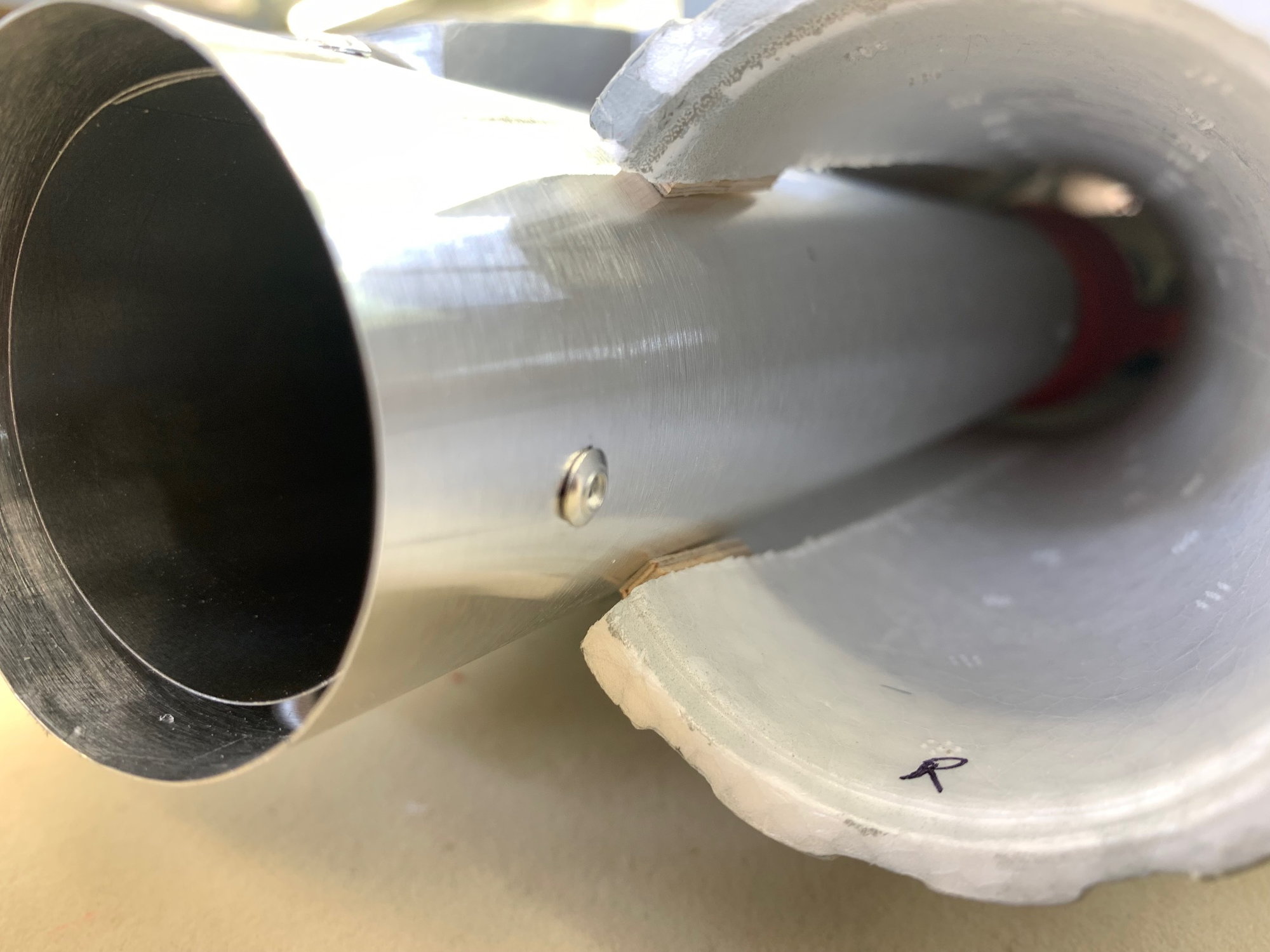
The rear of the foam intake separator had to be cut off to clear the aux tank pickup tube.

Aux tank pickup tube now clears the foam.
After final trim the front edges fit nice and flush with the foam bottom.
Tanks coated on outside with laminating epoxy.
WInged felt clunk installed viewed from bottom.
Clunk from side view.
Aux tank leak tested under water by blowing air into both tubes. No leaks detected.
Main tank tested with no leaks detected.
Tanks finished and ready to install
The rear of the foam intake separator had to be cut off to clear the aux tank pickup tube.
Aux tank pickup tube now clears the foam.
After final trim the front edges fit nice and flush with the foam bottom.
Last edited by Viper1GJ; 05-02-2023 at 02:56 PM.
05-02-2023, 03:19 PM
#23
Thread Starter
My Feedback: (20)
Fuel tubing install

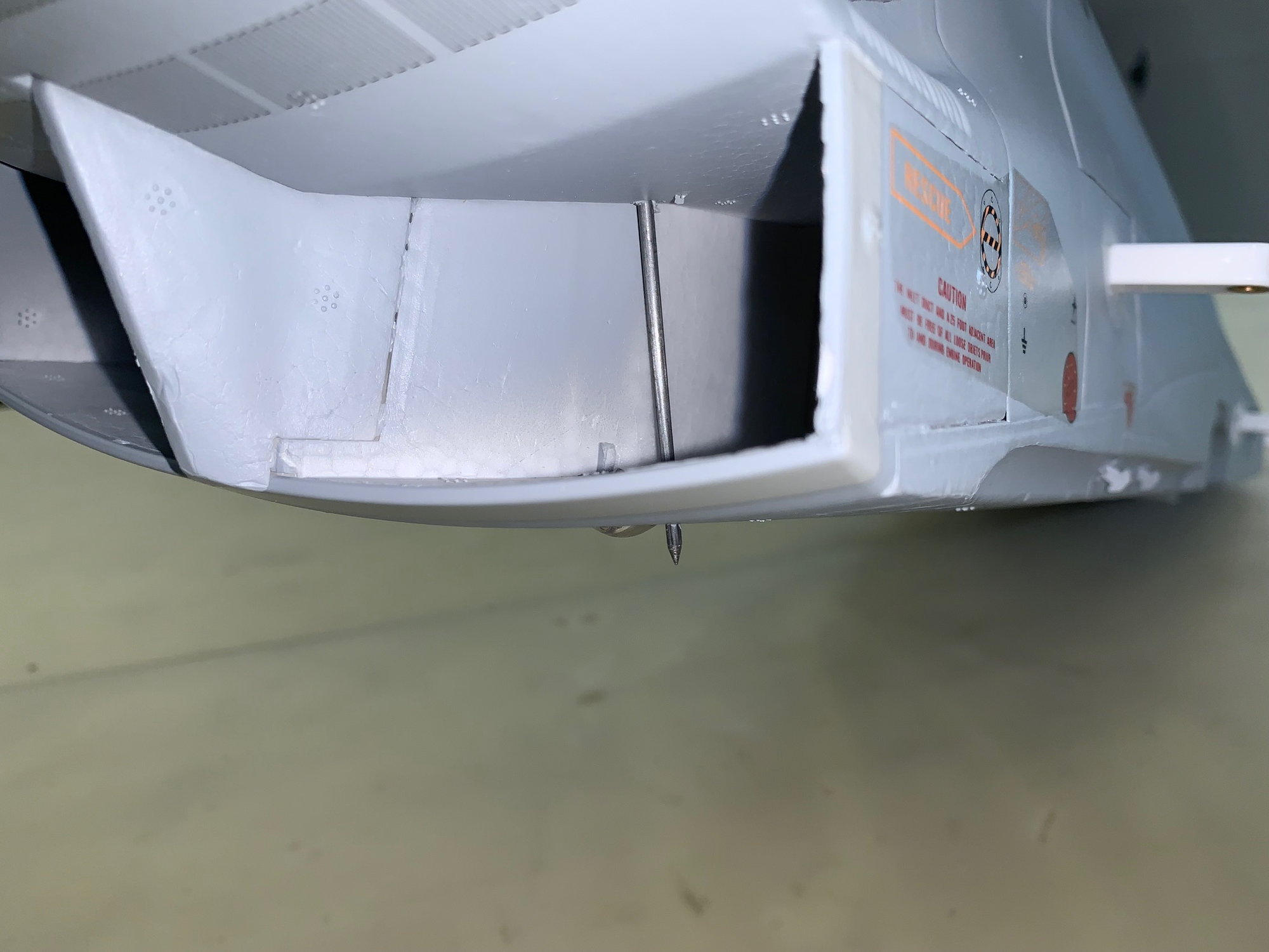
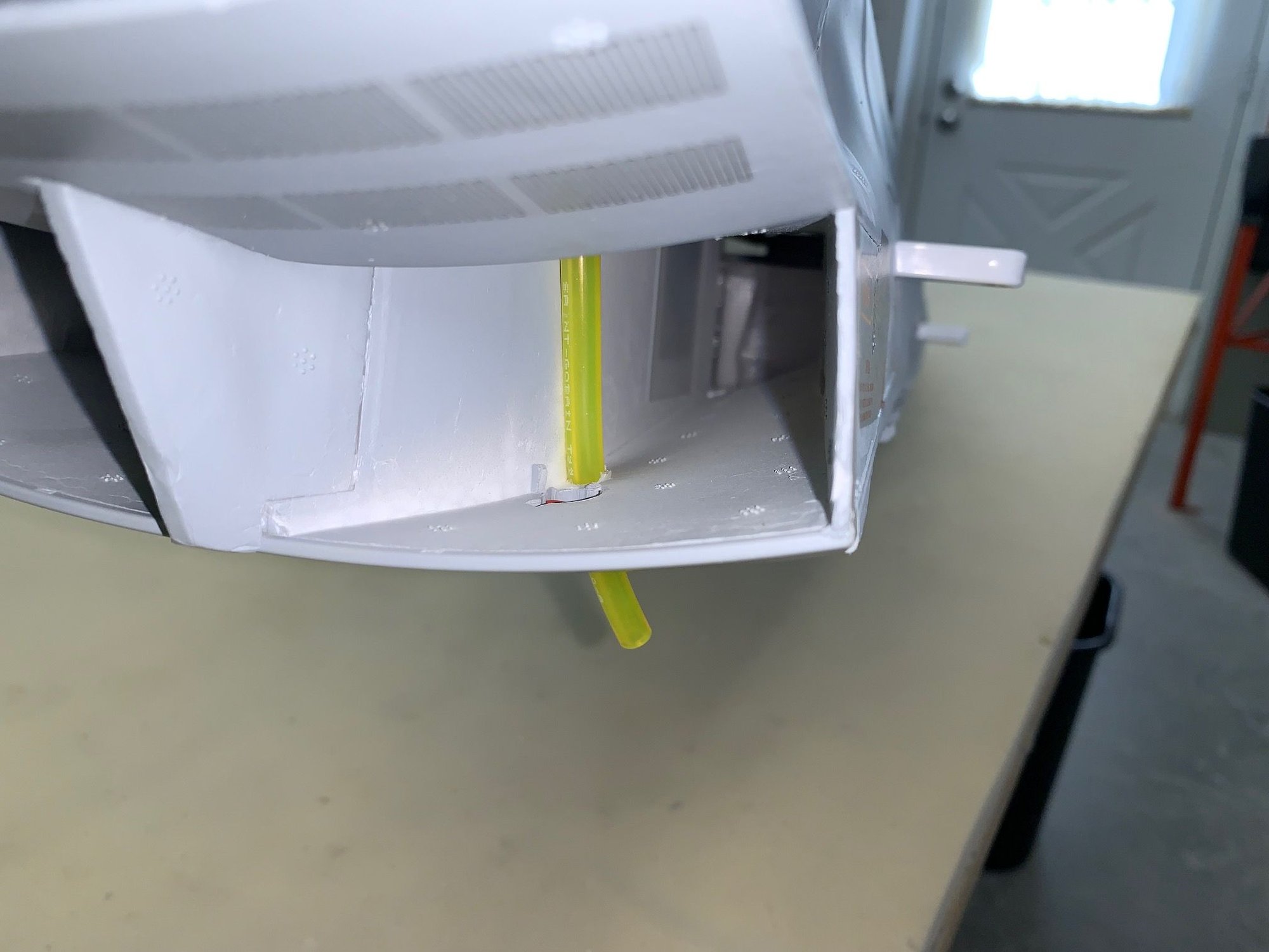
My initial plan to run the vent out the forward fuse was a tossed because I realized that any fuel blowing back in flight would blow back into the jet and possibly the turbine. So I located the vent tube further back and ran a punch through the foam out the bottom just behind the bottom strobe light.
Using the punch lined up the holes from the cockpit to outside the bottom skin.

I sharpened the edge of a thin wall aluminum tube to make a cutter the size of the 1/8" Tygon tubing. I ran the cutting tube back up the punch and cut a hole for the vent line.
The vent line has to run higher that the air trap tank to prevent possible draining out the air trap tank fuel through the fuel tanks since they are lower.

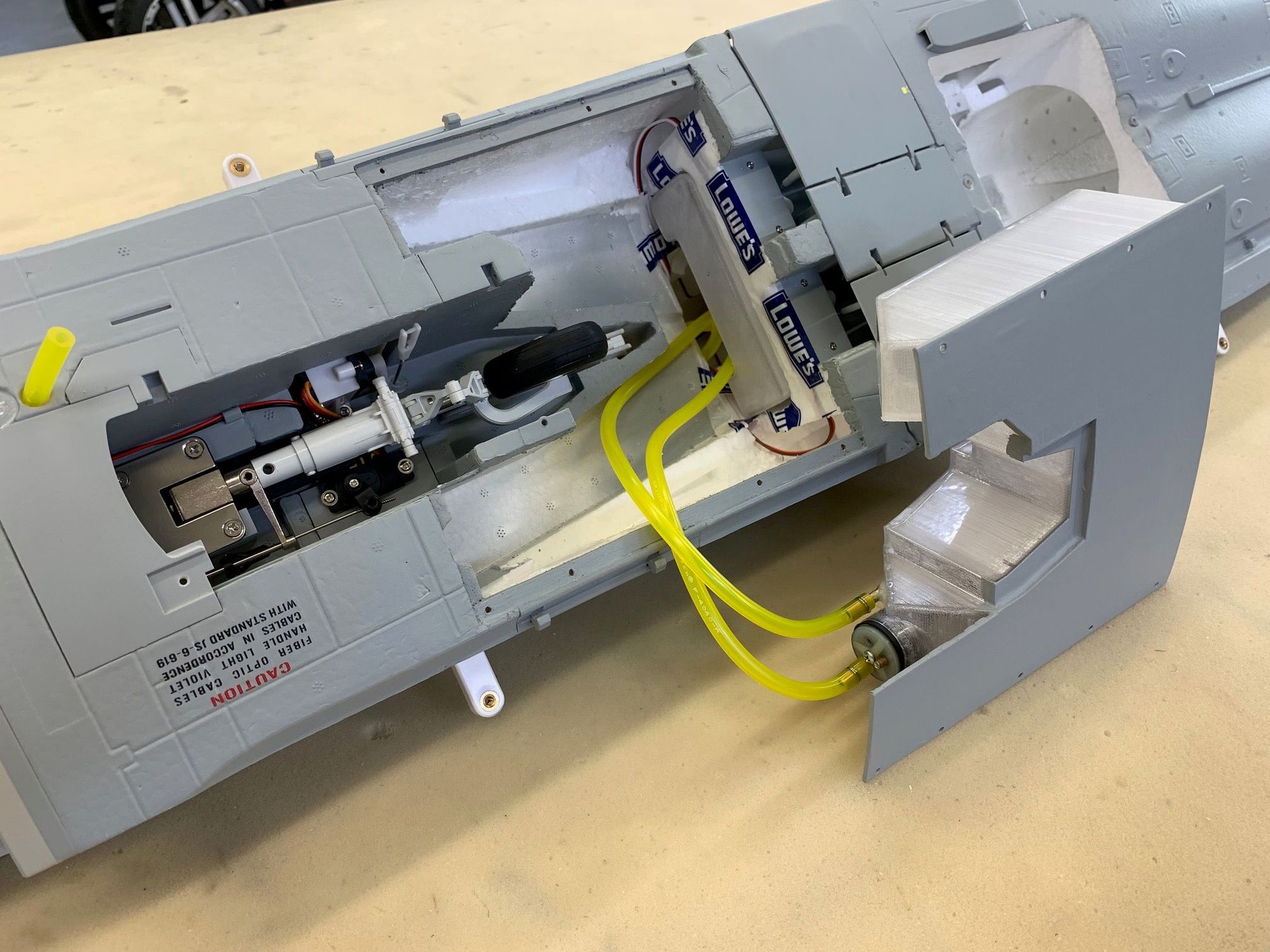
Vent line runs inside the intake and out the bottom of the fuse.
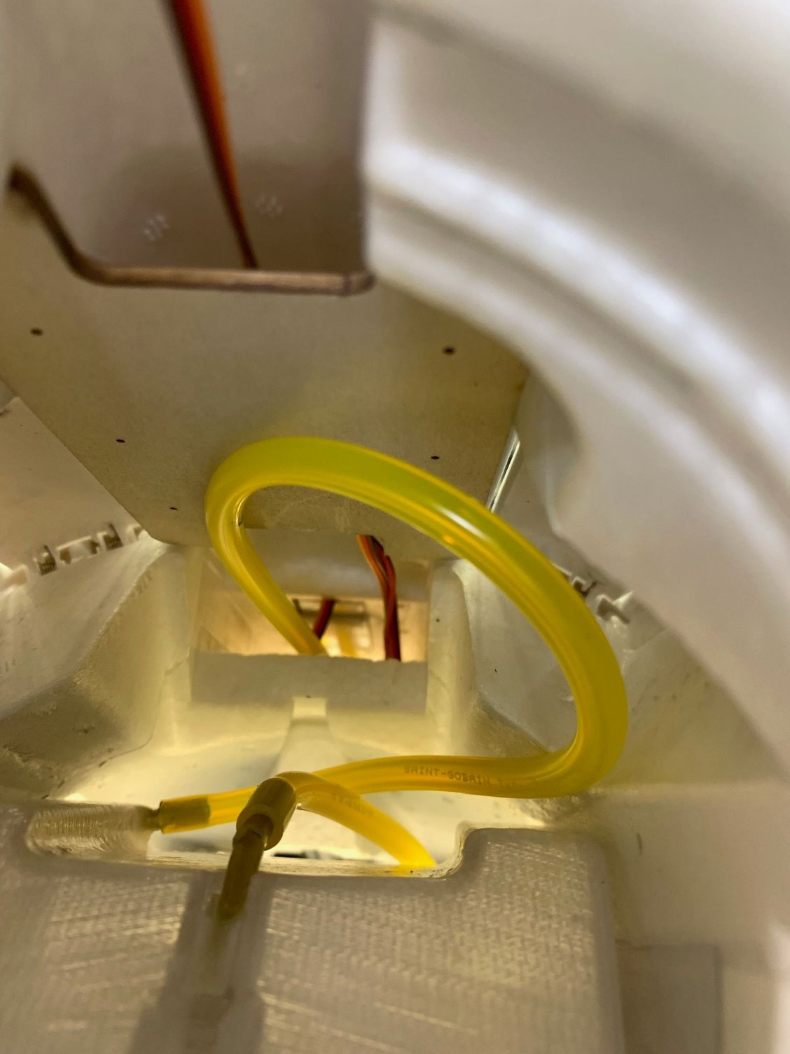
View from turbine bay forward.
Fuel system can be completely removed for service without disconnecting any tubing except from the turbine.
My initial plan to run the vent out the forward fuse was a tossed because I realized that any fuel blowing back in flight would blow back into the jet and possibly the turbine. So I located the vent tube further back and ran a punch through the foam out the bottom just behind the bottom strobe light.
Using the punch lined up the holes from the cockpit to outside the bottom skin.
I sharpened the edge of a thin wall aluminum tube to make a cutter the size of the 1/8" Tygon tubing. I ran the cutting tube back up the punch and cut a hole for the vent line.
The vent line has to run higher that the air trap tank to prevent possible draining out the air trap tank fuel through the fuel tanks since they are lower.
Vent line runs inside the intake and out the bottom of the fuse.
View from turbine bay forward.
Fuel system can be completely removed for service without disconnecting any tubing except from the turbine.
05-02-2023, 03:24 PM
#24
 05-03-2023, 04:44 PM
#25
Thread Starter
My Feedback: (20)
Fuel System Install
Bottom of main tank painted and VIton clunk line safety wired and installed in tank.
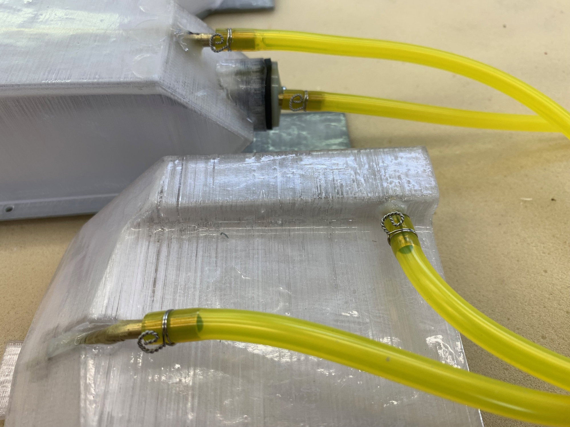
All Tygon connections safety wired
Aux tank and vent line installed. Main tank and fuel lines ready to install.

Main tank fuel stopper visible in right intake.
Vent line visible in left intake.
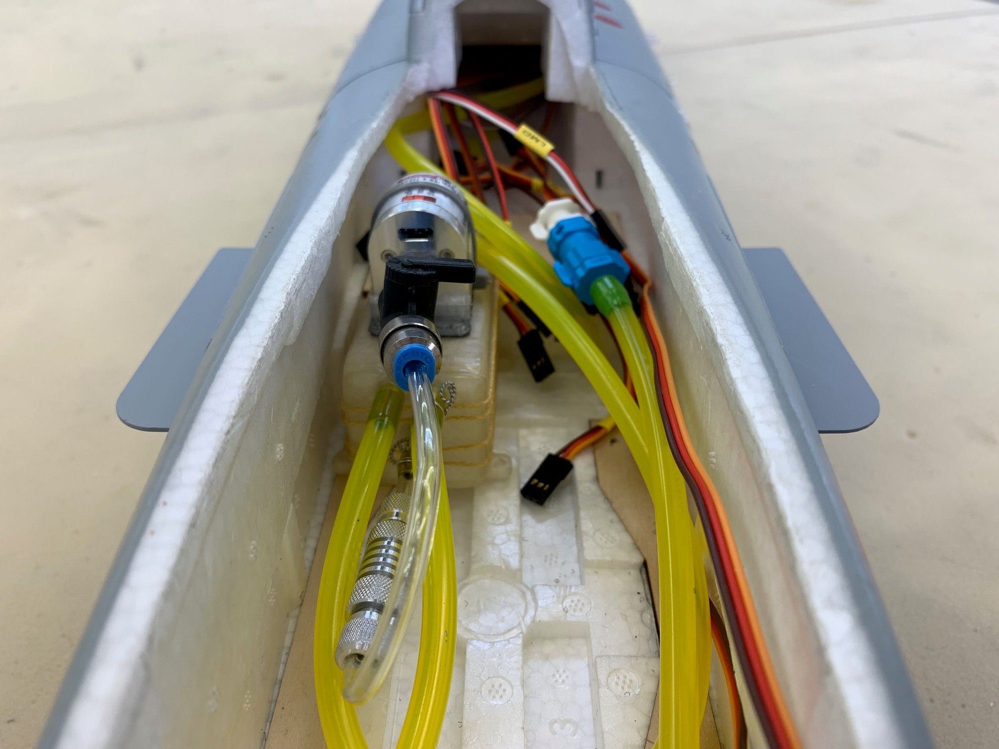
Air trap tank and pump dry fit in place.
Bottom of main tank painted and VIton clunk line safety wired and installed in tank.
All Tygon connections safety wired
Aux tank and vent line installed. Main tank and fuel lines ready to install.
Main tank fuel stopper visible in right intake.
Vent line visible in left intake.
Air trap tank and pump dry fit in place.
Last edited by Viper1GJ; 05-03-2023 at 05:05 PM.

