


GJC Aerojet F15C Eagle Build
 12-23-2022, 02:40 PM
#1

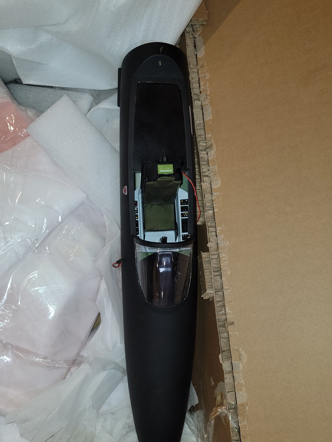
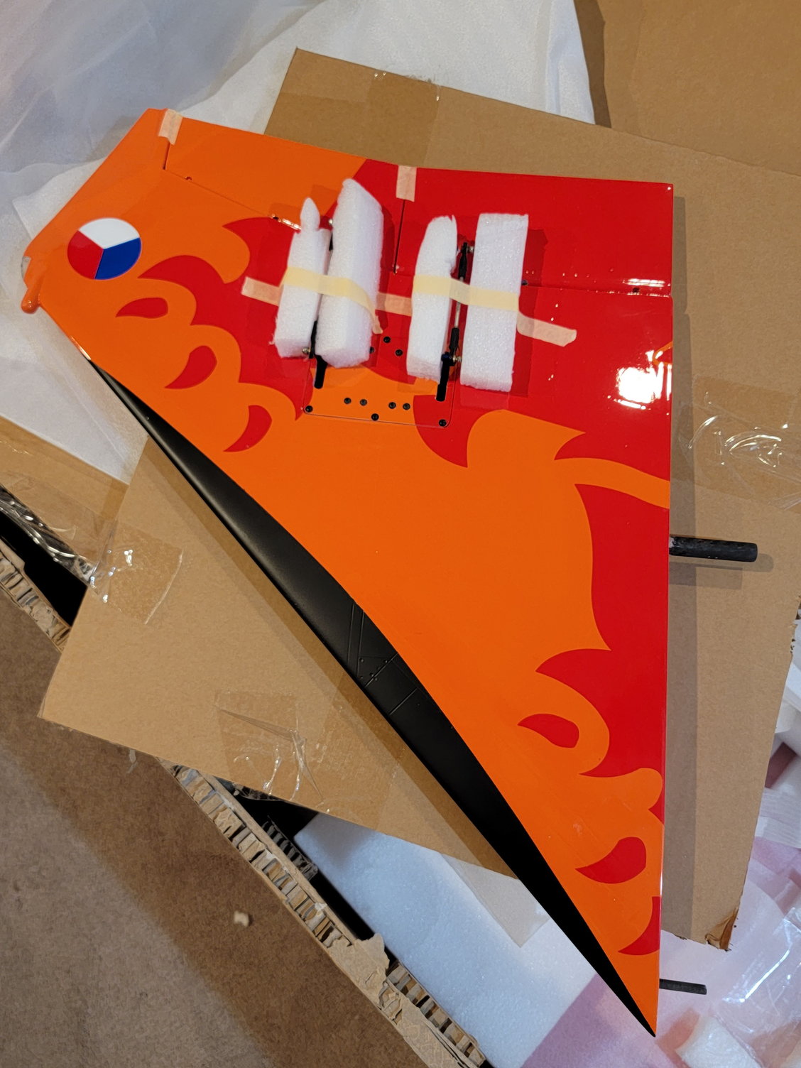
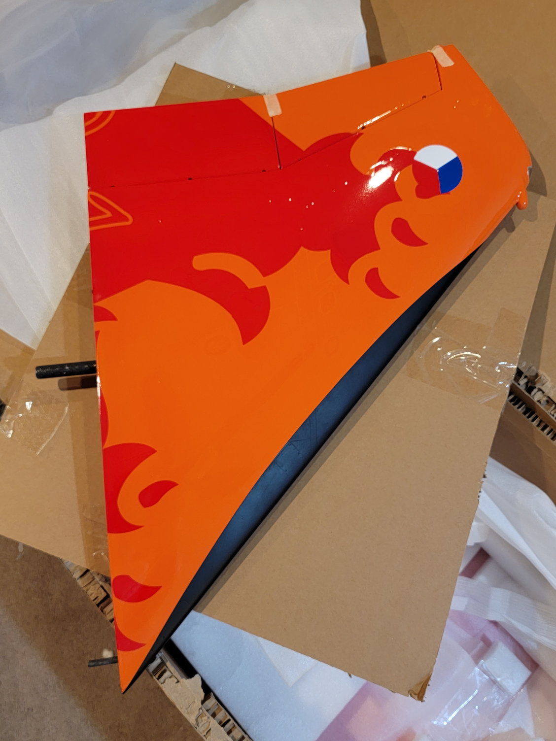
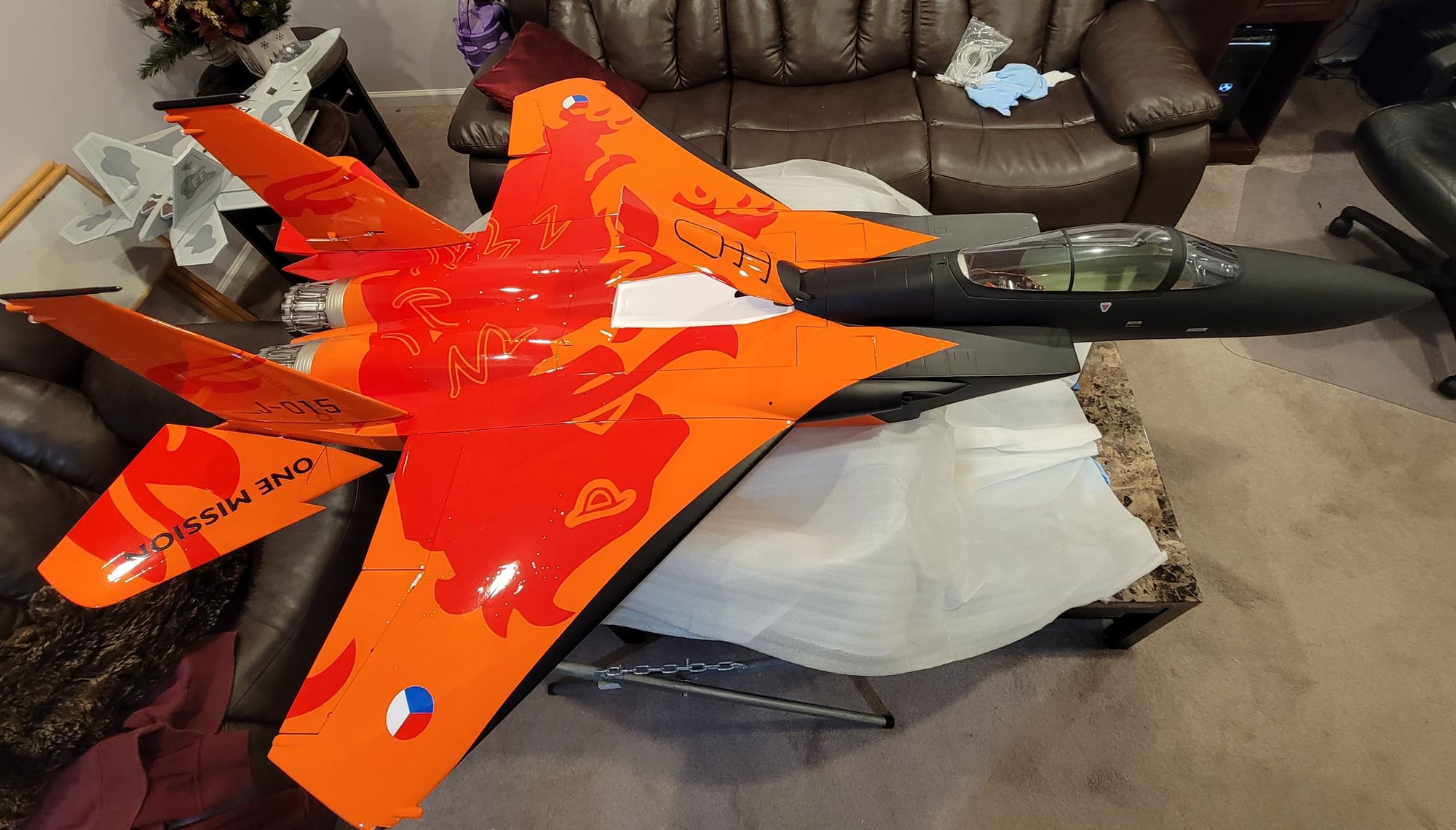
So I recently acquired a Global Jet Club Aerojet F15 C. I purchased it earlier this year, but as with everything since COVID, shipping took a bit for her to get here. The reason I went with this kit is because of the size, design, and the support from Global. I did not want something that was too large to transport easily, and that could be flown at my local field. Also, I considered the BH F15 but did not like how their fuel tanks were so far in front of the CG. That Aerojet version has two saddle fuel tanks and a center tank. The saddle tanks are placed over the CG. Therefore, the flight characteristics should remain the same whether the tank are full or empty. I plan on using a Swiwin 140n for thrust, a Smoothflite 16 for the gyro and power management, and a Digitech UAT. So, with the reason why I chose this kit and the equipment out of the way. Onto the build. The jet arrived in a decently sized, very robust cardboard box. It was well wrapped, and the standard foam wrapping with large pieces of foam were thrown in for support. As you can see from the pics, every component was individually wrapped. After unwrapping everything and inspecting the pieces, everything looked fairly good. There are a couple of small areas that would require some attention and touch up here and there, but nothing too concerning. After everything was unwrapped I normally assemble things to make sure that there is a good fit. Everything fits well, and the jet looks great. I picked the Dutch Lion color scheme just because I think it looks fantastic, and I always wanted a jet in that scheme. Before I start any build, the first thing I do is clean the surface and apply a polymer wax. I like to use Meguiars. This provides a protective finish in case of any mishaps with your glue or locktite. It also keeps the jet looking shiny and new. One thing I noticed immediately is that the front fuselage seemed to have a flatter finish than the rear or the wings, which was more of a matte. However, after applying a coat of wax, it shined up nicely, and now both sections match. I normally inspect all the glue joints for continuity and seams to make sure that it is a good fit. As you can tell from the pics, they did a really good job. Normally I have to get in with my hysol and gun and do some touch-ups. However, not so with this jet. It was great out of the box. The only issue I can see so far is that the thrust pipe bell mouth looks like it was bent in a bit. I am not sure if this occurred during packaging or shipping. As the bell mouth is aluminum, this should be an easy fix with a set of needle nose pliers. This F15 has a great look so far, and I am really looking forward to getting started on the build. Pardon the mess. Had to move to the family room due to the holidays and losing my work area.
Thanks for looking,
Tone
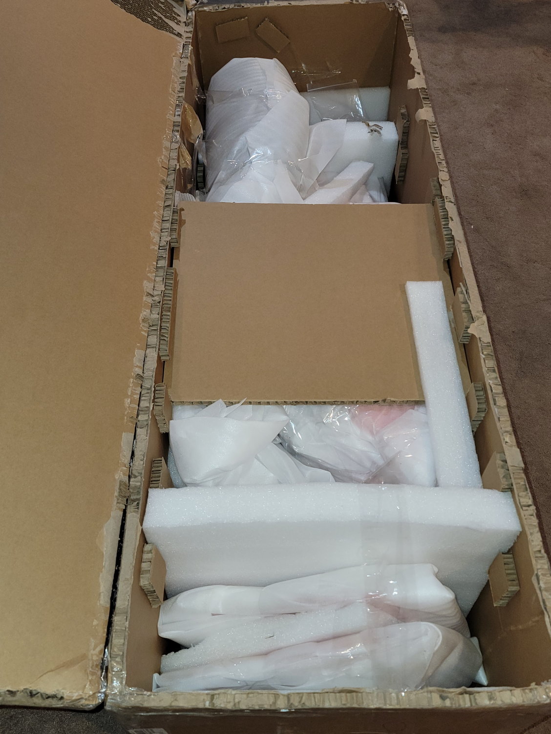
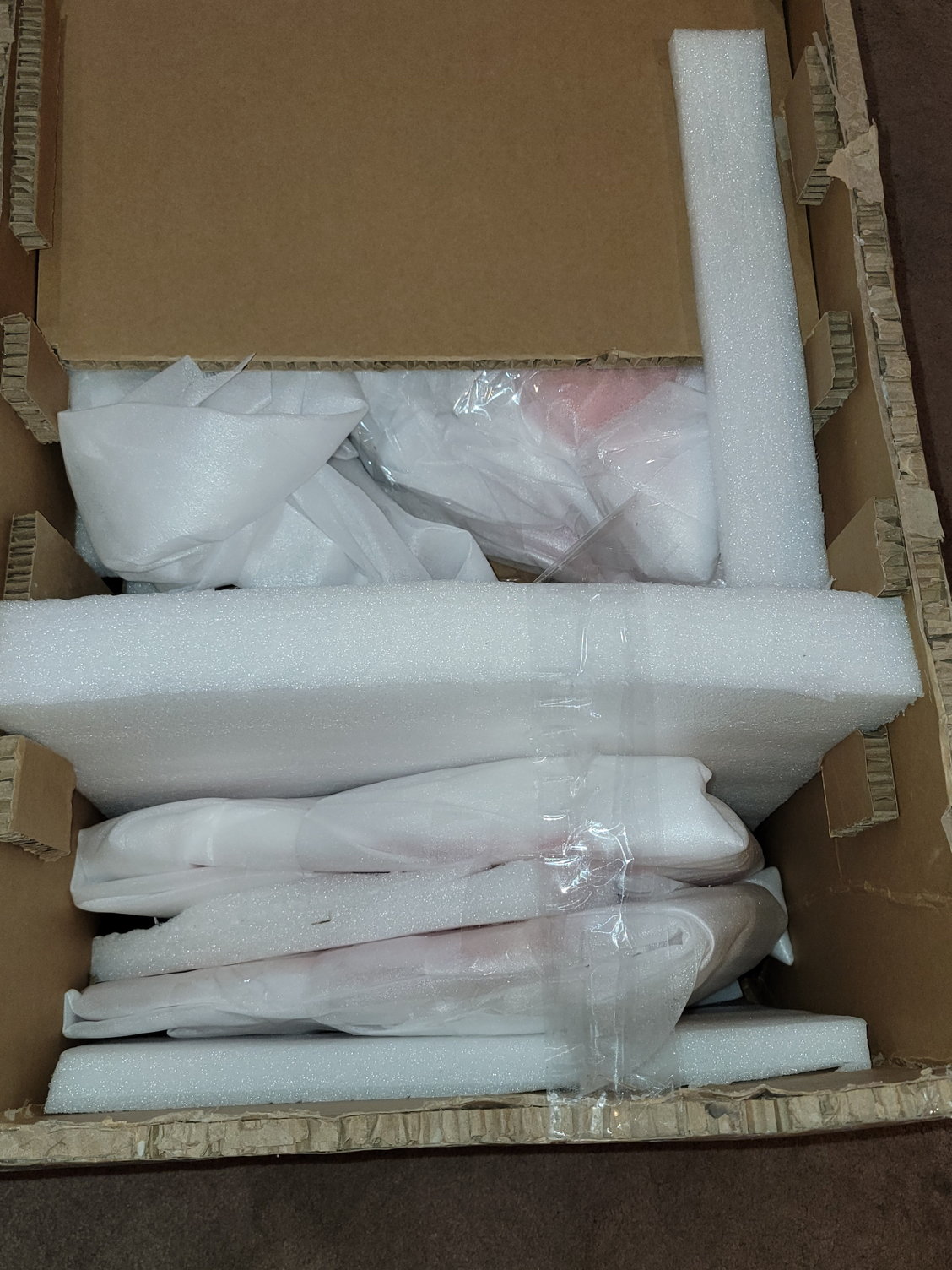
Everthing seems to be packaged well.
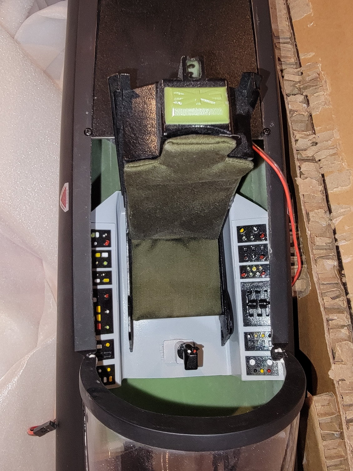
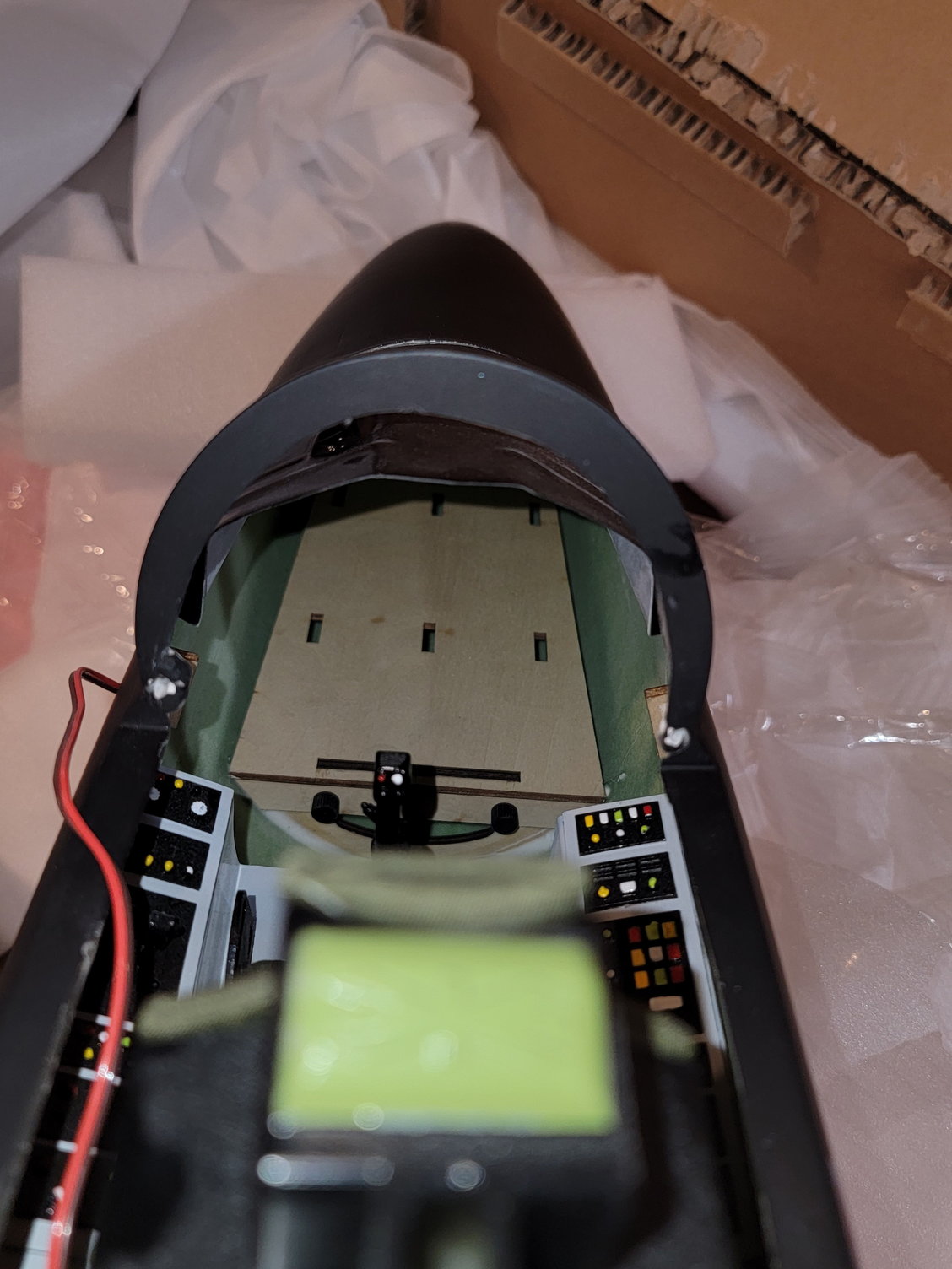
I was not expecting actual cushions on the seat.

This is the hardware bag. It came with the Y fittings, clear Tygon and even wire wrap to secure the fuel lines.

These are already glued and ready to go.
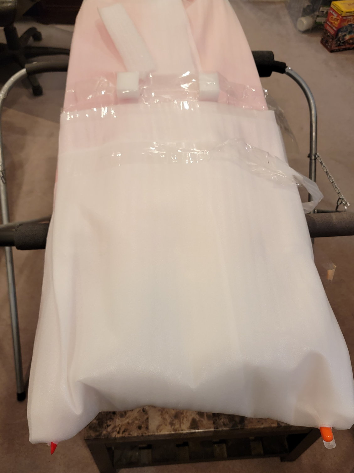
As yoy can see, everything came nicely wrapped.
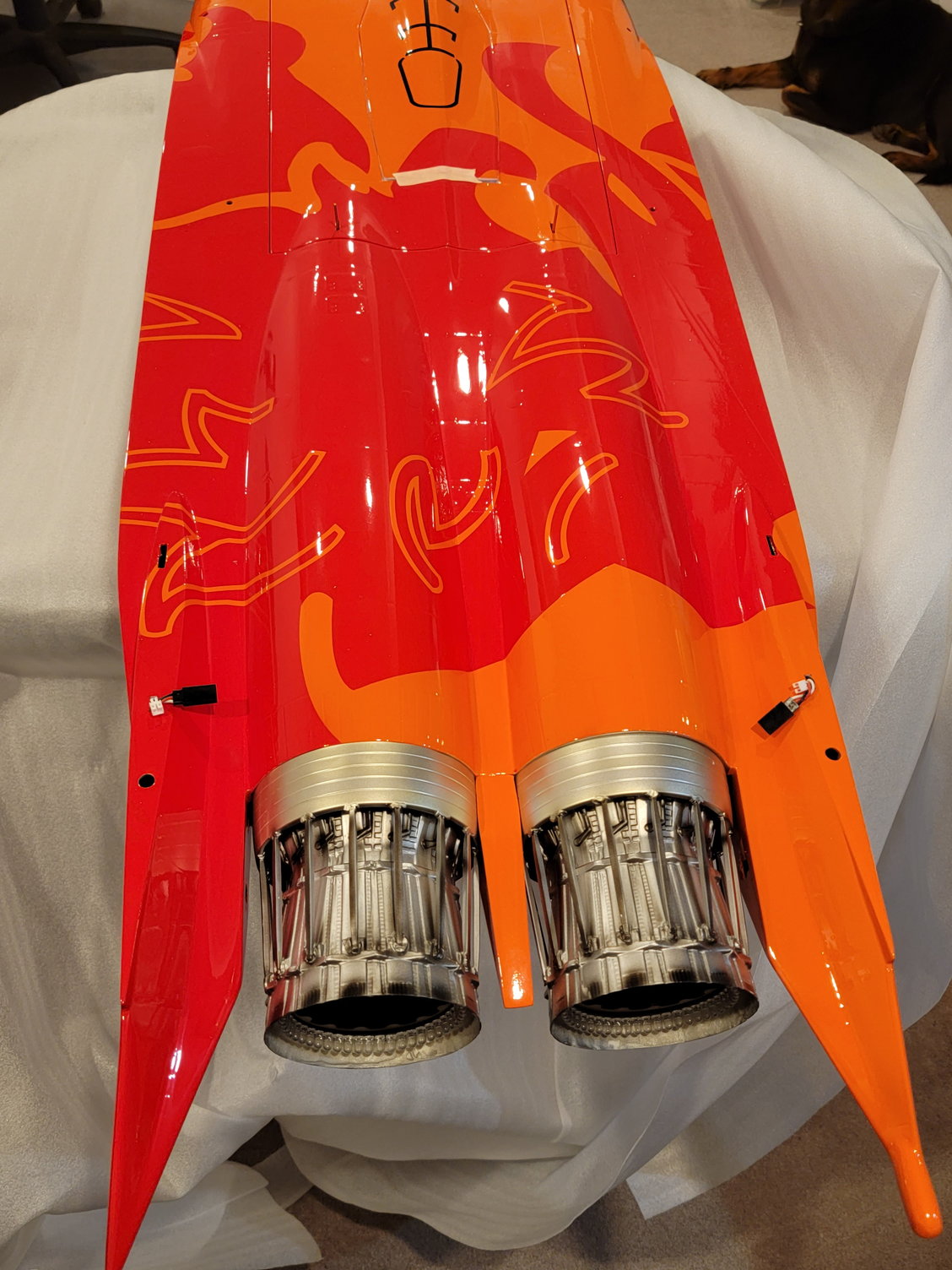
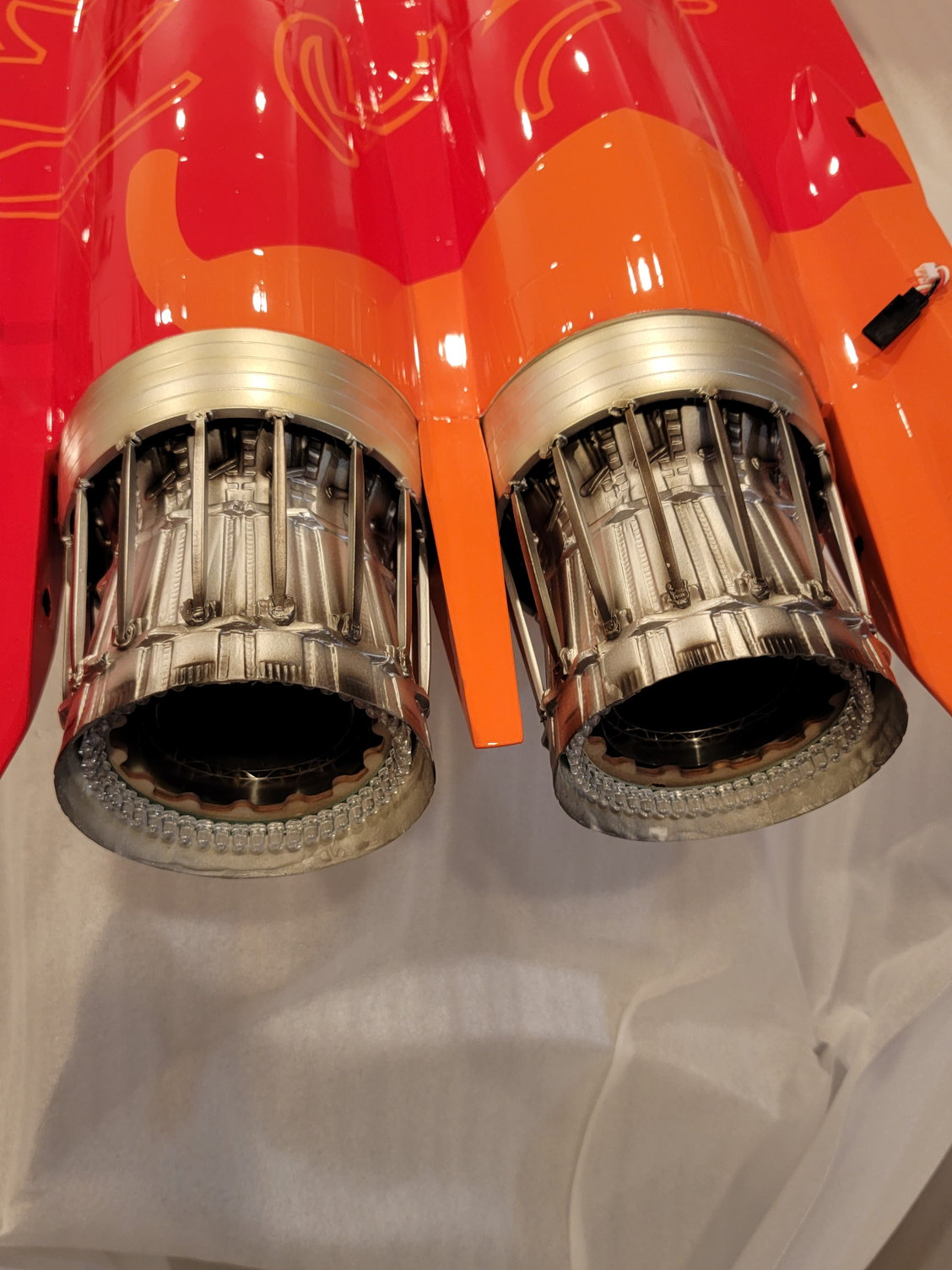
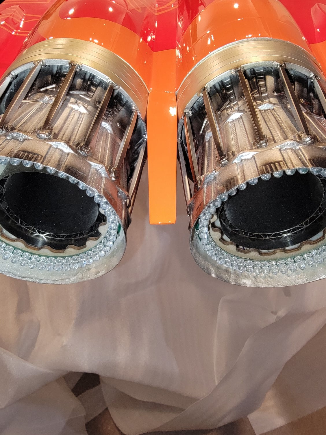
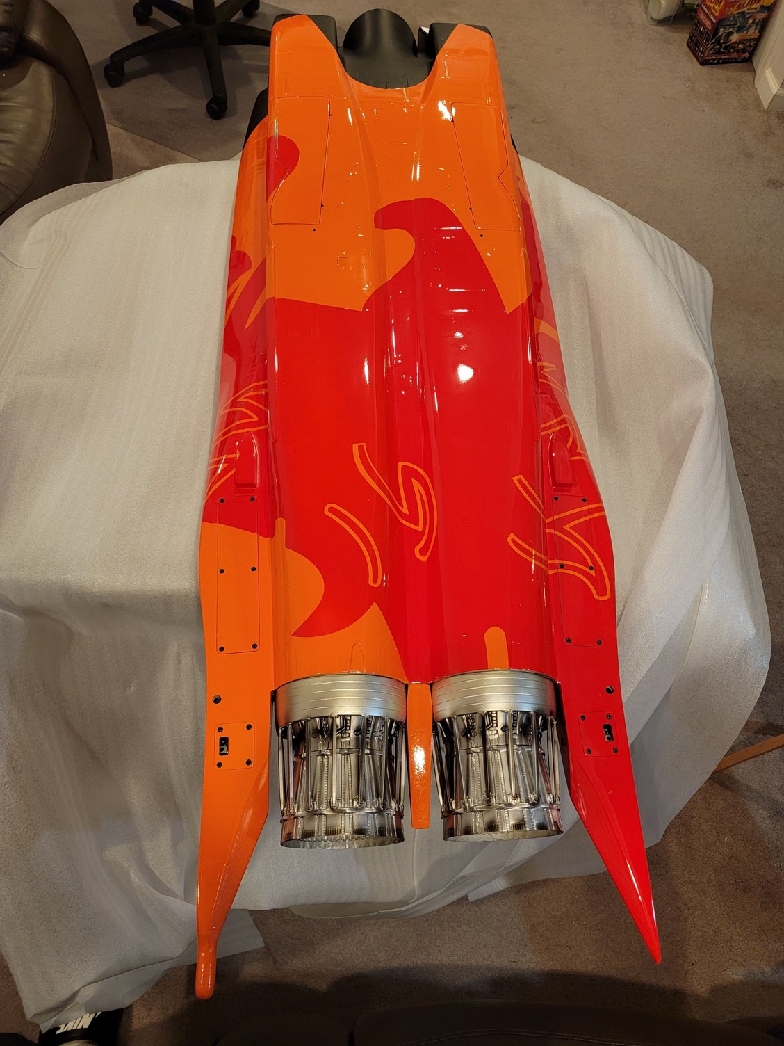
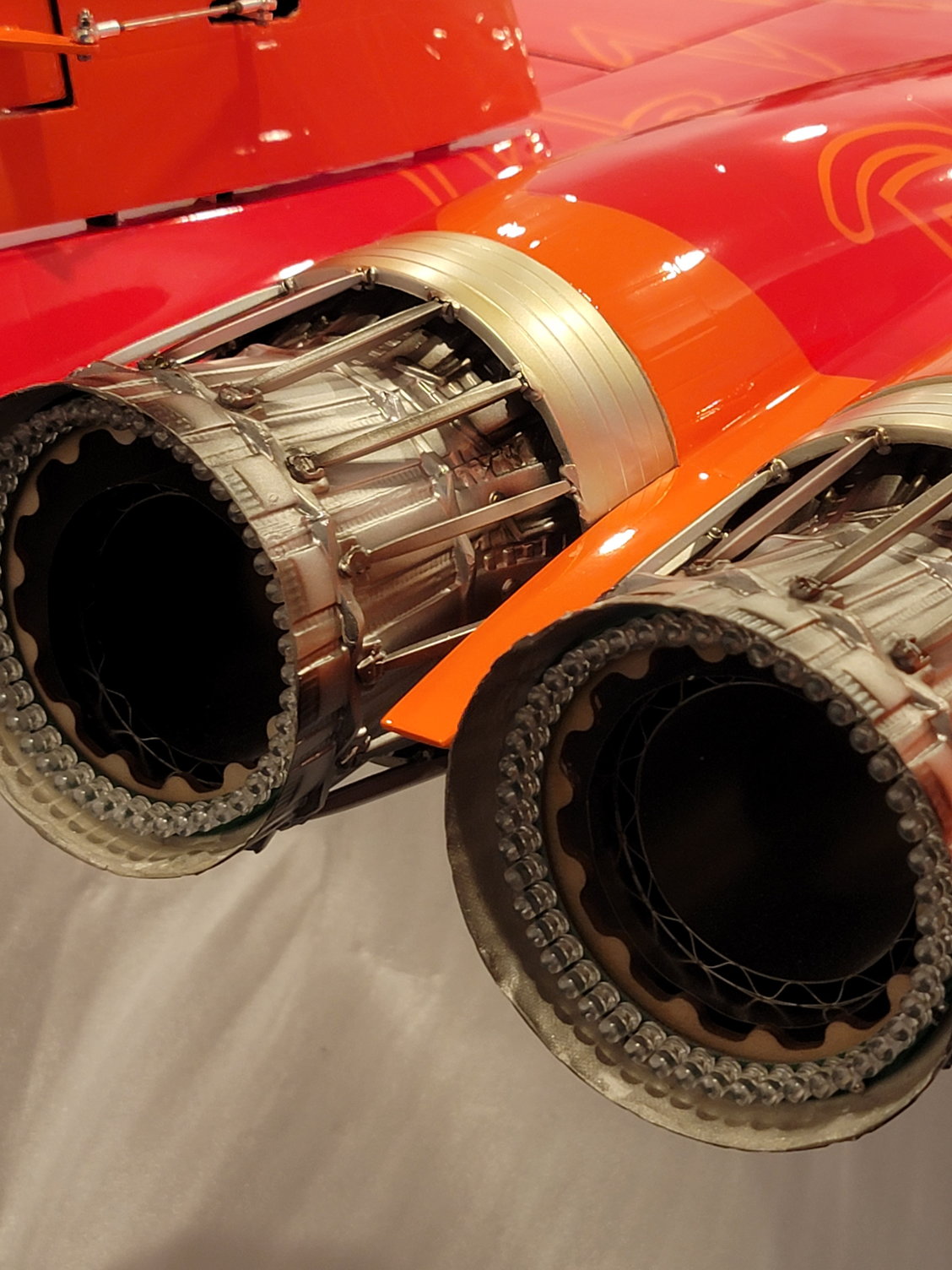
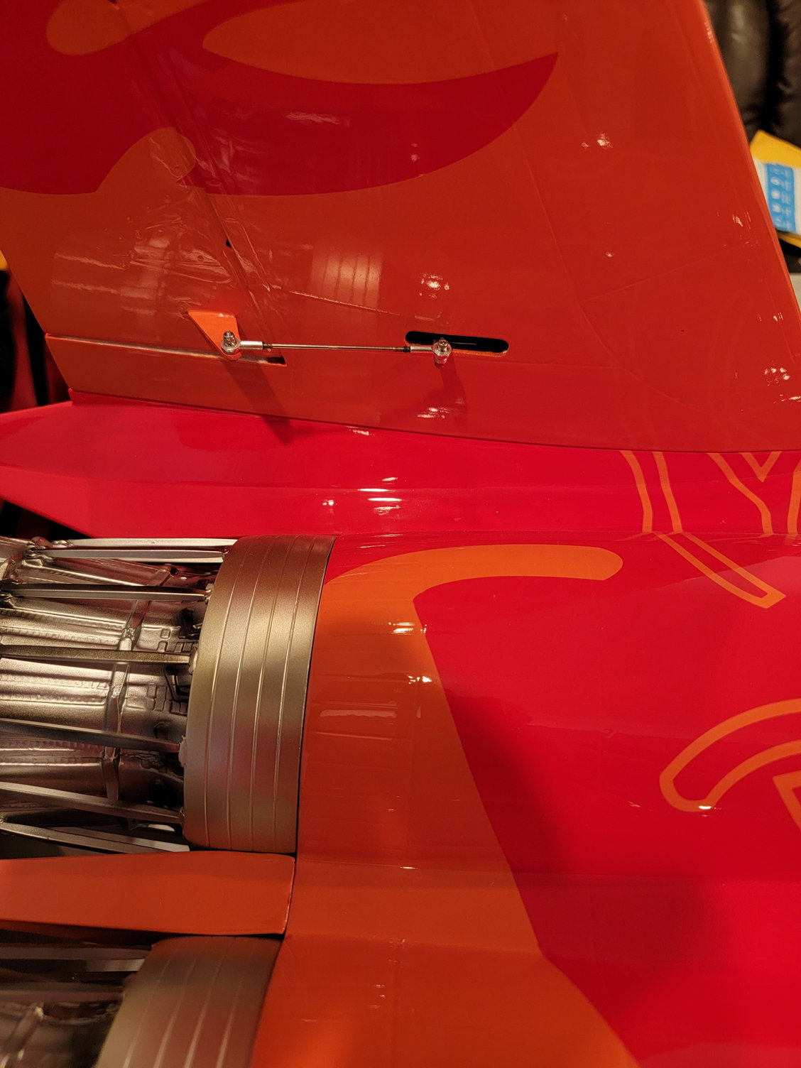
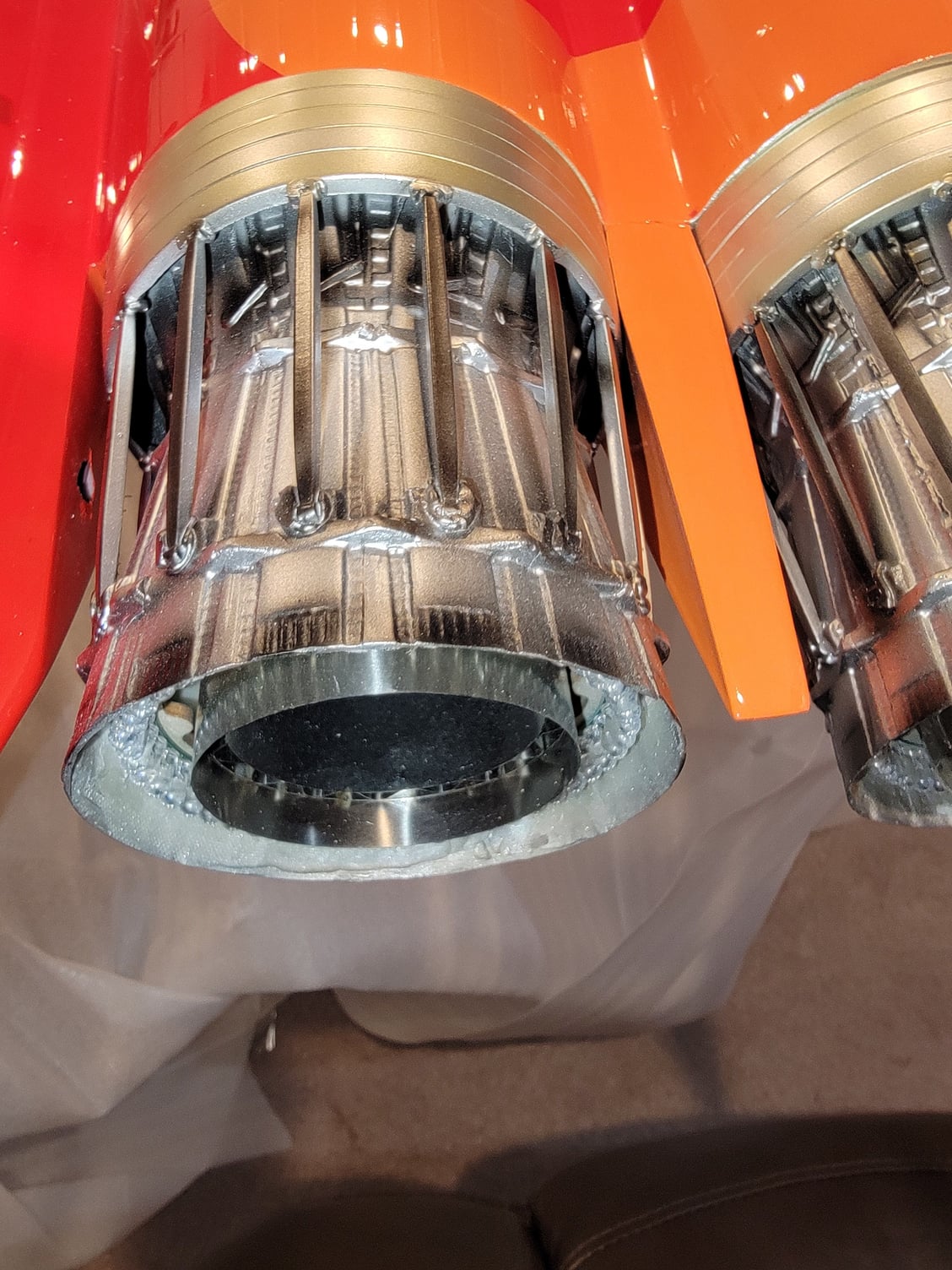
Great detail on the exhaust.
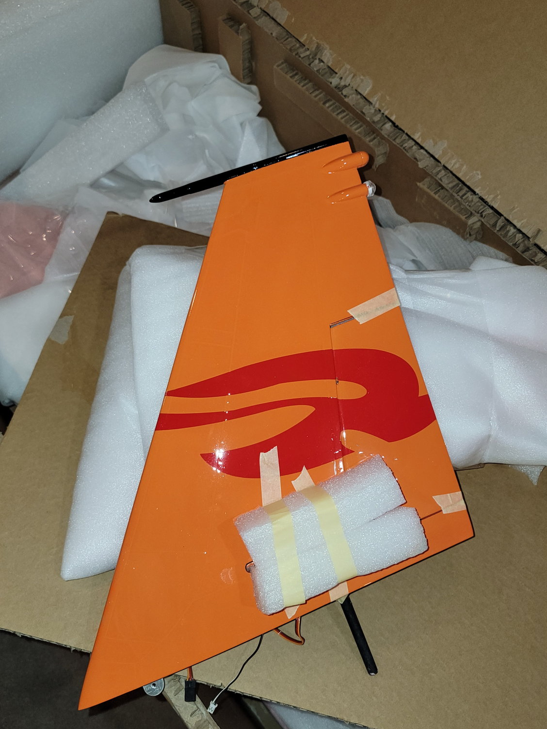
Love the white under the functional air brake.

Here is the front tank. Hold 800ml
Underneath the airbrake and top hatch.
Came with dual afterburner lights.
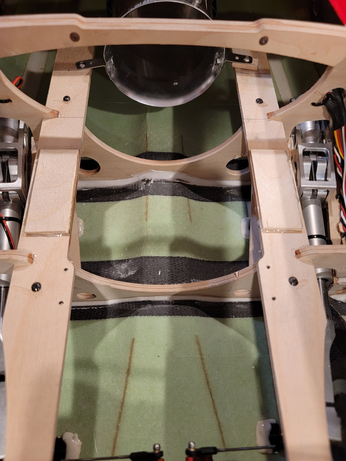
Nice sturdy crossbar to support the formers.
Pardon the mess. Has to move to the family room due to the holidays and losing my work area.
Thanks for looking,
Tone
Everthing seems to be packaged well.
I was not expecting actual cushions on the seat.
This is the hardware bag. It came with the Y fittings, clear Tygon and even wire wrap to secure the fuel lines.
These are already glued and ready to go.
As yoy can see, everything came nicely wrapped.
Great detail on the exhaust.
Love the white under the functional air brake.
Here is the front tank. Hold 800ml
Underneath the airbrake and top hatch.
Came with dual afterburner lights.
Nice sturdy crossbar to support the formers.
Pardon the mess. Has to move to the family room due to the holidays and losing my work area.
Last edited by Agrav8ed; 12-23-2022 at 03:19 PM.
 12-23-2022, 02:50 PM
#2
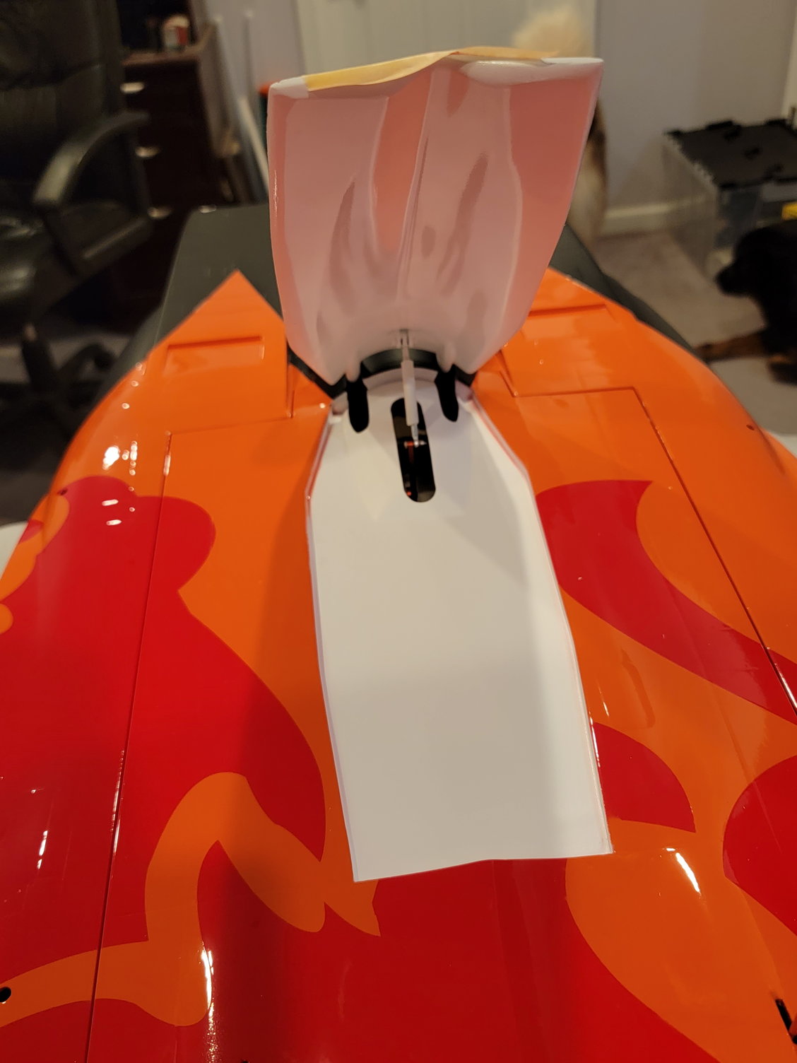
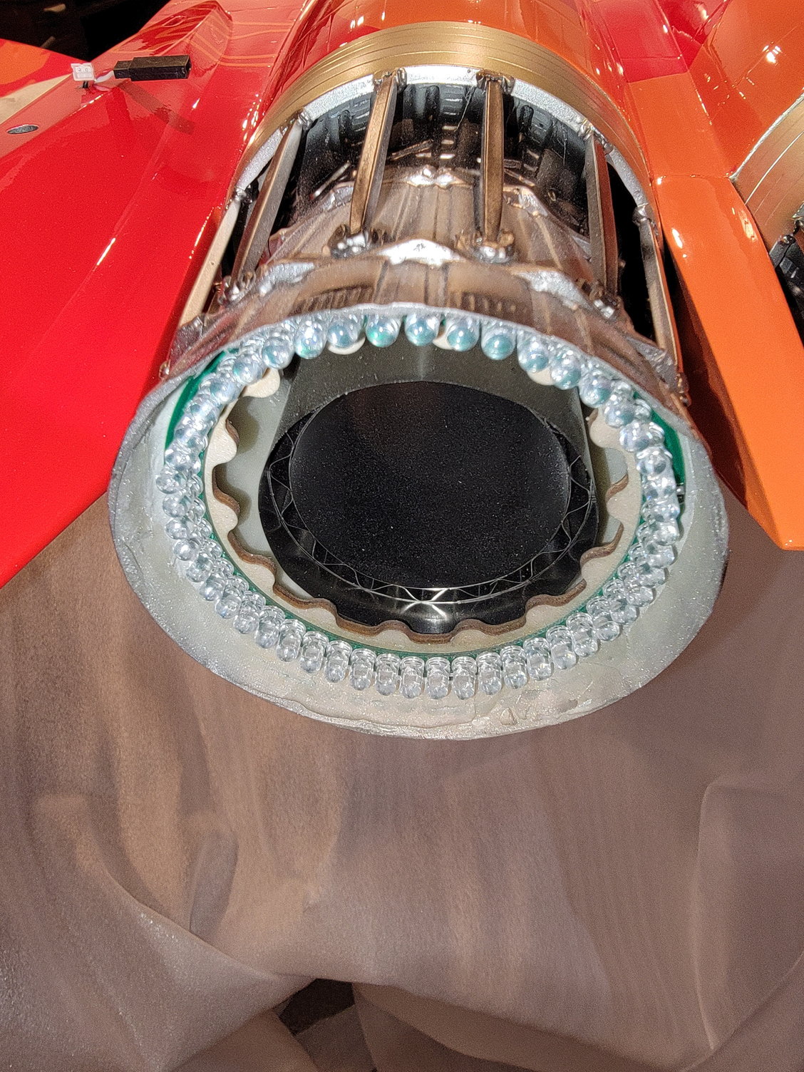
Thrust pipe The thrust pipe is a dual outlet type due to the exhaust of the F15. While straightening the bell mouth and mounting tabs, I noticed that when a pipe was installed, it was not rotated exactly 90 degrees, so it would not make complete contact with both rails without putting a strain on the exhaust. On a single outlet pipe, this is not an issue, as the pipe can just be rotated. However, on a dual outlet pipe, it cannot be rotated, and when whoever at the factory drilled the holes and mounted the pipe, this little detail was missed. Now, this could have been fixed by removing the pipe and drilling new holes or drilling a new hole for the mounting bracket, but it was only off by about 6 to 7 mm. Therefore I opted to add a small wooden spacer on the left-hand side before screwing the pipe to the turbine rail. This spacer will take up the 6-7 mm gap and still allow for secure mounting of the exhaust pipe while keeping it centered.
Thanks for looking,
Tone
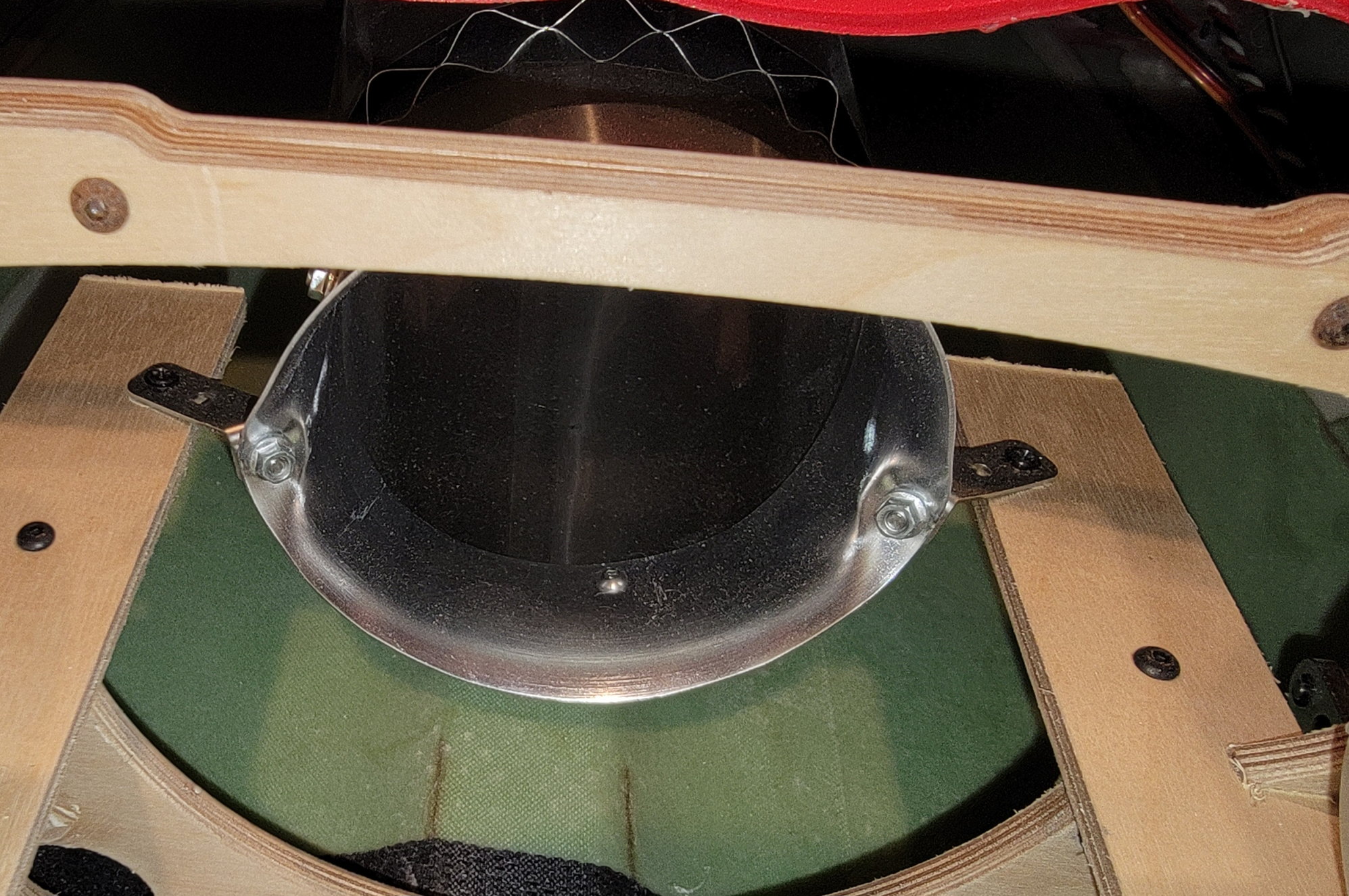
You can see in this pic how the bell mouth was bent back a bit and the tabs are facing backward. The metal is in good shape and should be able to be massaged back in place.
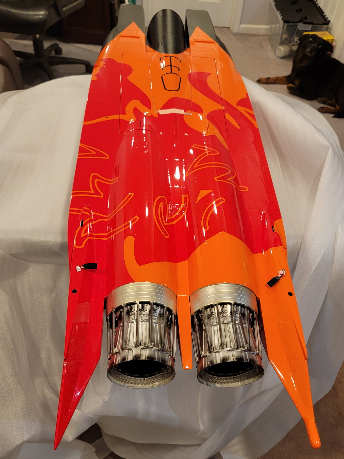
Here you can see the thrust pipe mounted. The bell mouth was massaged back and the tabs are facing forward. You may be able to see the spacer block under the left tab.
Thanks for looking,
Tone
You can see in this pic how the bell mouth was bent back a bit and the tabs are facing backward. The metal is in good shape and should be able to be massaged back in place.
Here you can see the thrust pipe mounted. The bell mouth was massaged back and the tabs are facing forward. You may be able to see the spacer block under the left tab.
Last edited by Agrav8ed; 12-23-2022 at 03:11 PM.
12-23-2022, 03:08 PM
#3
PNPI received the PNP version that comes with the servos, linkages, wiring, navigation lights, dual afterburner lights, a working air brake, cockpit, and landing gear already installed. However, I learned from my RC car days that "plug and play" is just a word and to go over everything if you want the best results. Hence, the build thread. It is better to be safe than sorry. I checked all the linkages and all the servo installations and would advise you to do the same. There was no locktite used to install the servo arms. However, the arms were installed accurately and are of good quality. Therefore, they were removed, and blue locktite was applied. The elevator servos were a bit difficult to reach. Therefore, I applied a small amount of Goop to the side of the screw and the servo arm to serve in a place of locktite and stop any vibration issues or unwanted rotation of the screws. The kit utilizes nylon locknuts on all of the linkages also. However, I disassembled these too, and installed a 3 mm washer on the ball link side as a safety precaution to prevent any issues with the ball link coming off accidentally. This kit uses mini servos for the ailerons and flaps, micro servos for the rudder, and standard-size servos for elevators and steering. The aileron and flap servos are mounted using plastic L brackets. One thing I tend to do and might build is to remove the servos, clean and roughen the mounting plate, and apply a little E-6000 or Goop adhesive between the servo plate and the servo. This allows them to become one unit, resists lateral force, and takes a little of the pressure off of the mounting brackets. It also allows you to slip a knife in between a plate and the servo and cut out the rubberized adhesive for removal in the future. I also use a couple of tiny drops of goop between the servo mounting plate and the wing before screwing it down for the same reason. All screw holes in the wood get a few drops of thin CA to help harden the wood.
Thanks for looking,
Tone
Love how tight this fits.
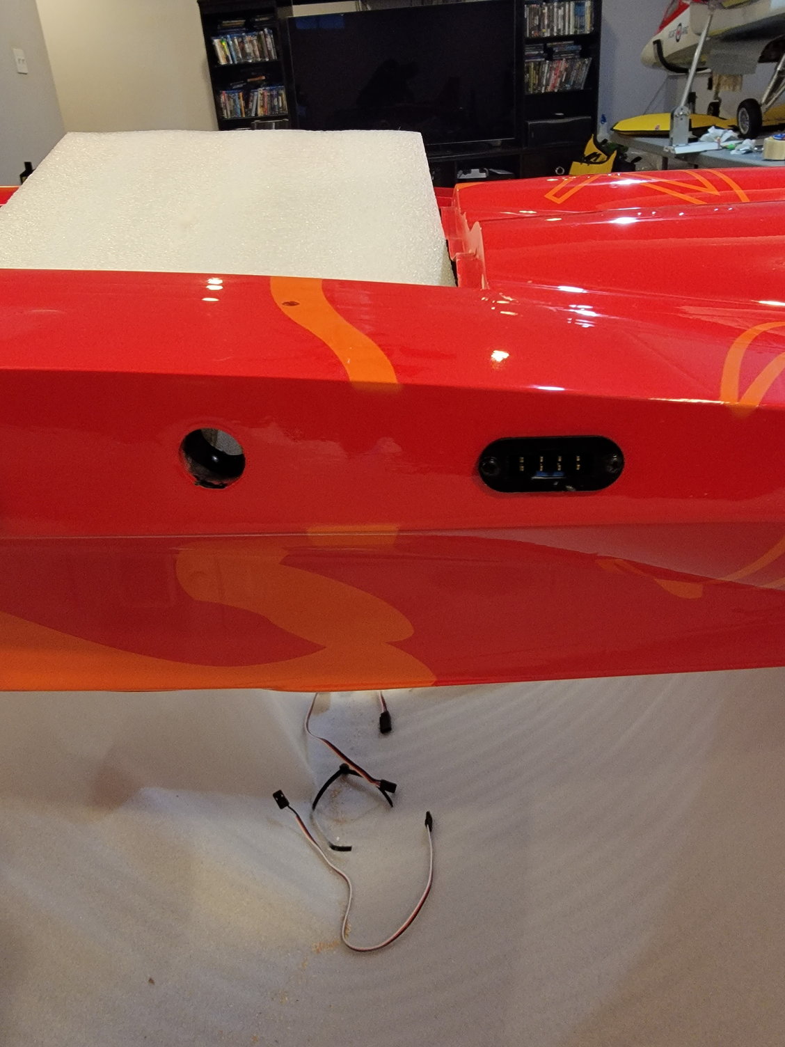
The MPX 8 pin connector is already mounted and secured.

Vertical view of the elevator. It has a nice 2mm nylon friction washer so that everything is evenly spaced and rotates freely

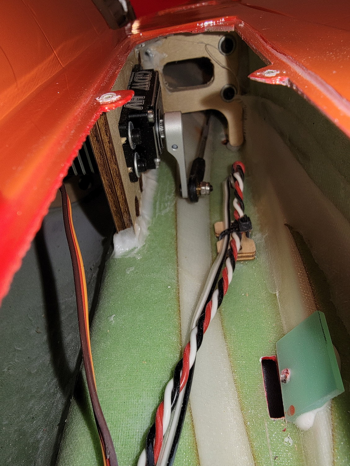
Linkage for the elevators. I replaced the 3mm allen screw with a longer one and a nylon locknut to ensure it never backs out or gets lost.
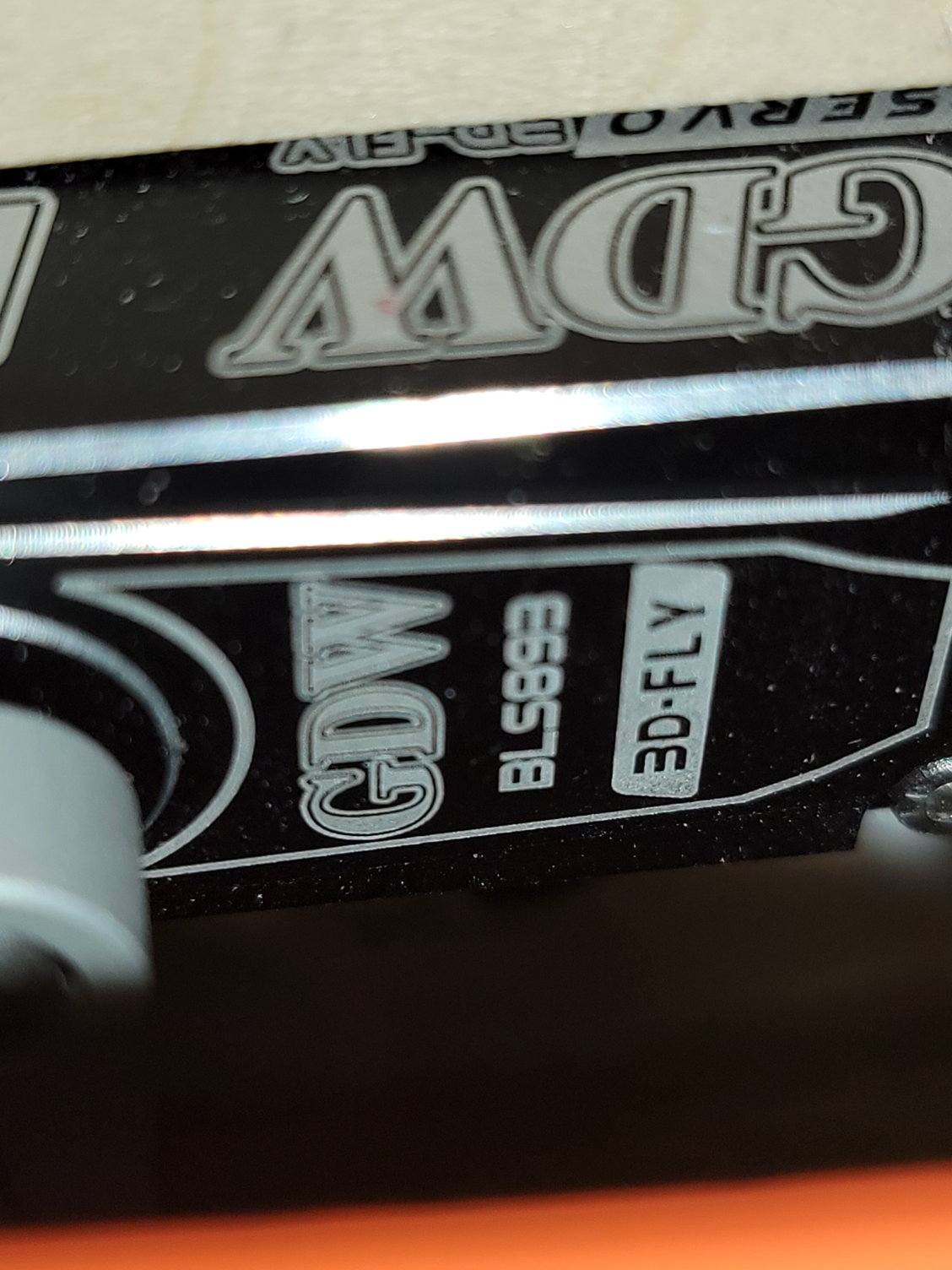
38kg servos for the elevators.
I love their design for the elevators. There is a aluminum cage o side with bearing on lateral and medial sides to hold and support the elevators. Best desigm of any jet I have built so fair and I have built many.
Love how tight and clean the rudders mount
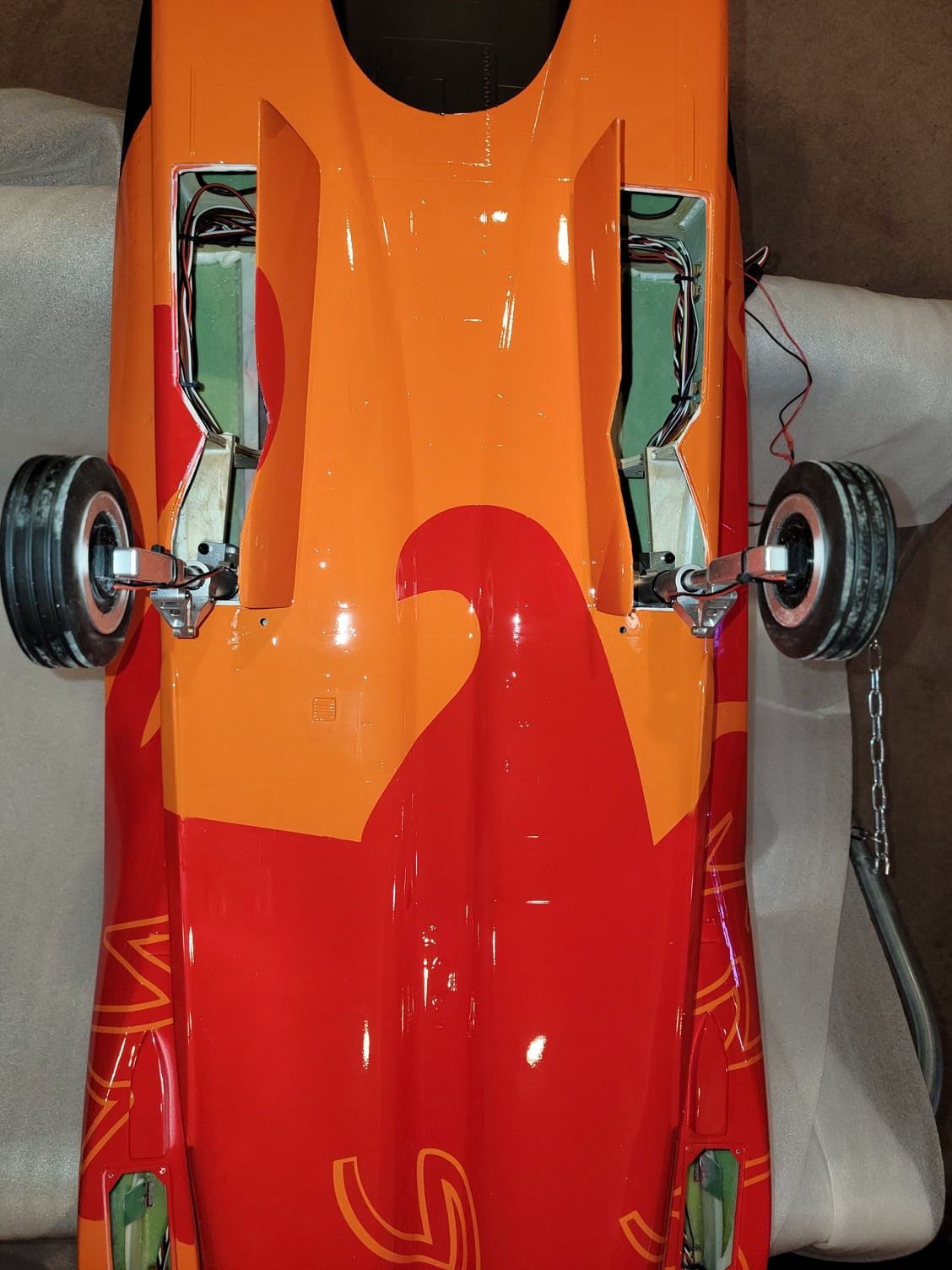
Gear works great. The wheels are much larger than I was expecting and should do great for grass ops.
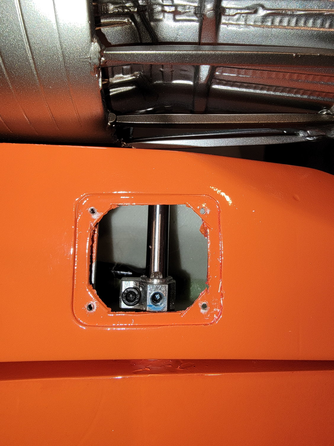
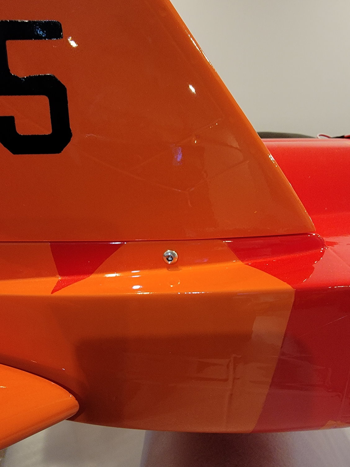
Here you can see the access hole to tighten the vertical stabs. The elevator will hide this whole when moving. Someone really thought this out.
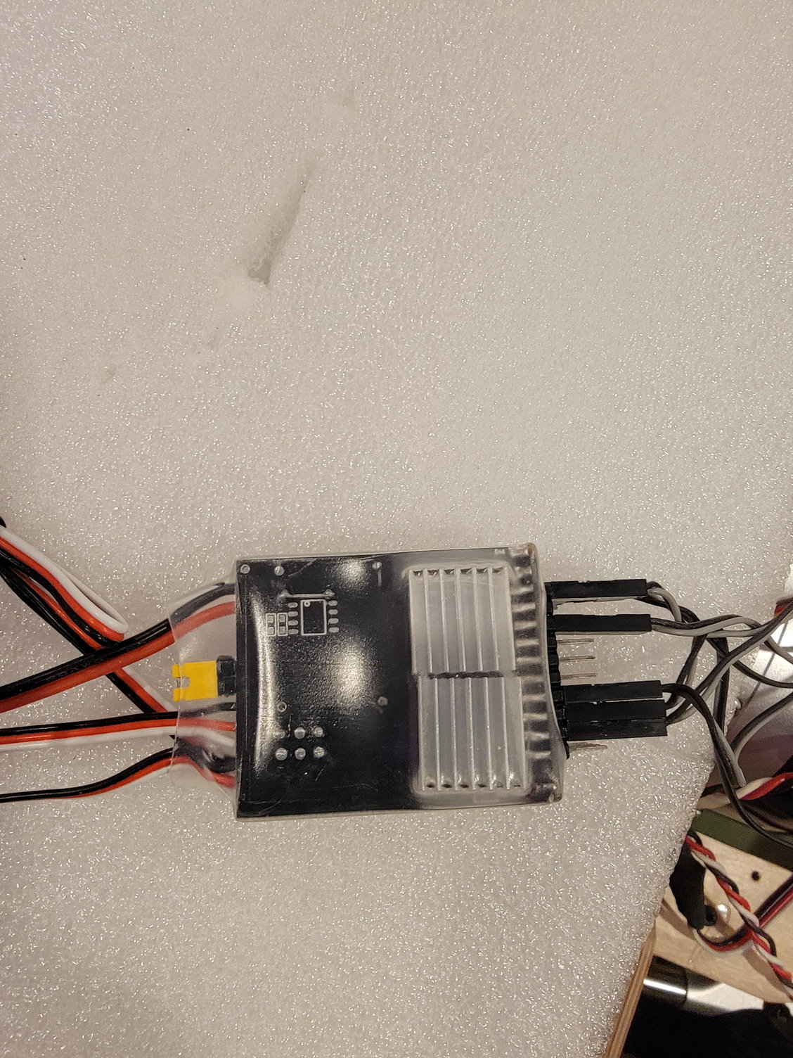
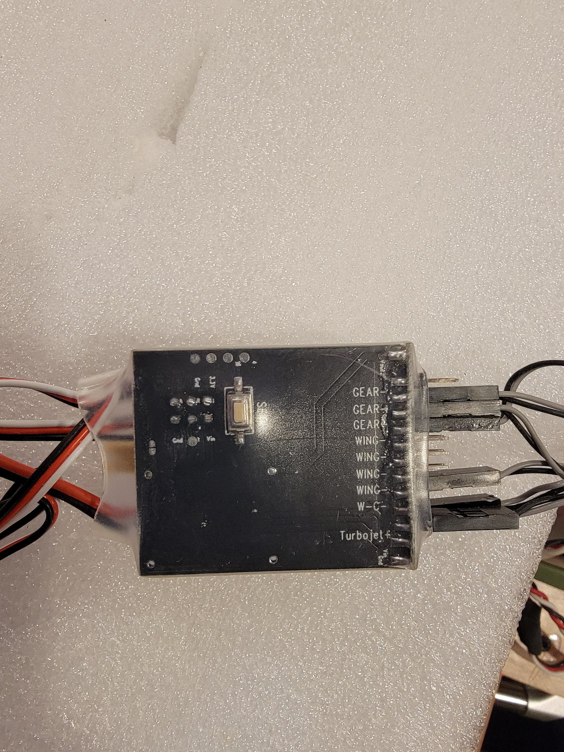
This controller operates the landing lights, nav lights, strobe and afterburners.
Thanks for looking,
Tone
Love how tight this fits.
The MPX 8 pin connector is already mounted and secured.
Vertical view of the elevator. It has a nice 2mm nylon friction washer so that everything is evenly spaced and rotates freely
Linkage for the elevators. I replaced the 3mm allen screw with a longer one and a nylon locknut to ensure it never backs out or gets lost.
38kg servos for the elevators.
I love their design for the elevators. There is a aluminum cage o side with bearing on lateral and medial sides to hold and support the elevators. Best desigm of any jet I have built so fair and I have built many.
Love how tight and clean the rudders mount
Gear works great. The wheels are much larger than I was expecting and should do great for grass ops.
Here you can see the access hole to tighten the vertical stabs. The elevator will hide this whole when moving. Someone really thought this out.
This controller operates the landing lights, nav lights, strobe and afterburners.
Last edited by Agrav8ed; 12-23-2022 at 03:12 PM.
12-23-2022, 03:14 PM
#4
That's all I have for now. Will post more later after I get some more shopping done and presents wrapped. If you have any questions or want to see anything in particular please let me know.
Thanks,
Tone
Thanks,
Tone

 12-23-2022, 04:05 PM
#6
Thanks,
Tone
12-24-2022, 06:51 AM
#8
Thanks,
Tone
 12-24-2022, 09:38 AM
#9

Wait, thats backwards being just a little short from what I always understood was better to help with pos/negative pressures that will actually help pull the heat out. As well as help overall air flow through and around the pipe?

The following users liked this post:
Bob_B (12-25-2022)
12-25-2022, 08:44 AM
#13
The kit quality is good. I think I one of the first run kits and so far I have been pleased. It is advertised as Aerojet but I am not sure what factory it comes out of.
thanks,
Tone
thanks,
Tone
The following users liked this post:
Viper1GJ (12-28-2022)
 12-29-2022, 02:35 PM
#16
No flight. Engine runs were great, range check perfect then came the taxi tests...good acceleration, perfect tracking then when I pulled throttle to idle and applied brakes it flamed out. Ran it up again, shook bubbles out and tried it again.....and again and again. 4 times it did the same thing. After checking the UAT (full) I decided to start it again and hold the nose down.....poof! I think the UAT sock is loose from pickup. Wont be able to get back on it until mid Feb. I'm bummed. Removing the fuel system in this thing is not a fun task.
12-29-2022, 03:14 PM
#17
No flight. Engine runs were great, range check perfect then came the taxi tests...good acceleration, perfect tracking then when I pulled throttle to idle and applied brakes it flamed out. Ran it up again, shook bubbles out and tried it again.....and again and again. 4 times it did the same thing. After checking the UAT (full) I decided to start it again and hold the nose down.....poof! I think the UAT sock is loose from pickup. Wont be able to get back on it until mid Feb. I'm bummed. Removing the fuel system in this thing is not a fun task.
thanks,
Tone
12-29-2022, 04:52 PM
#18
Wing bracket
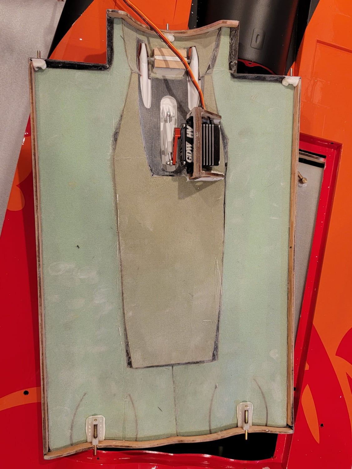
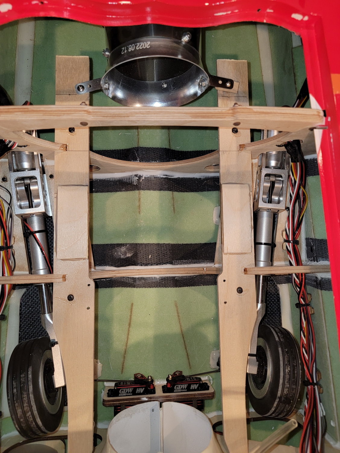
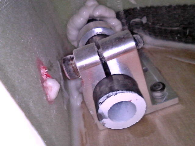
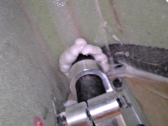
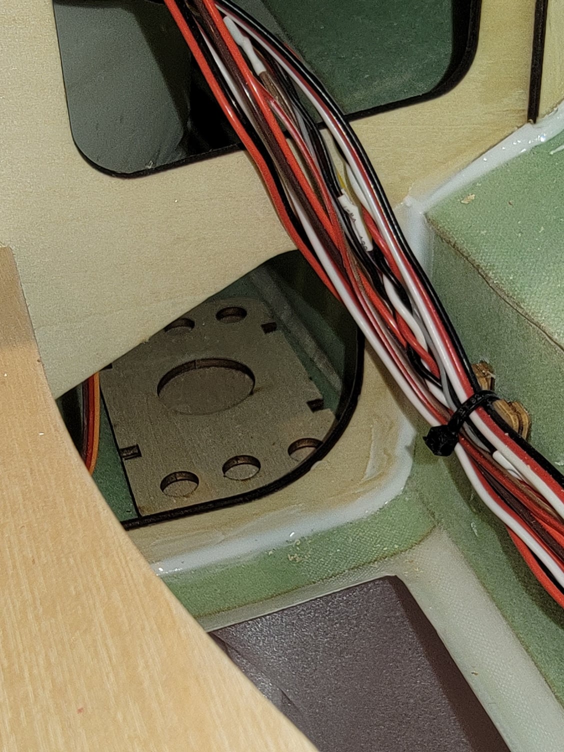
One thing I noticed and would advise everyone to check is the aluminum bracket that holds the wings. My left wing was a bit loose and required some attention. The right seemed okay. After looking into things, it became evident that the aluminum bracket that is mounted to the main former was a bit loose. This allowed the way some vertical movement and play. It is a bit hard to reach the screws; however, it is worth the effort to ensure these brackets are tight and secure as they are a significant component in securing the wing. The front anti-rotation pin was fine. I had to loosen the zip ties that secure the wire loom and remove the turbine rails to get to the bracket. From there, it was an effort in patience to remove the hardware, but it was doable. Once the bracket was removed, it appears that they also used glue to adhere the bracket to the former in addition to the allen screw and nuts; however, it does not appear that mine took very well. Therefore, my plan is to use a strong adhesive like hysol or E-6000 on the bracket before tightening and reinstalling. He also plans to install 3 mm washers before the nylon locknuts to increase the surface area. These efforts may not be necessary for everyone, but I would strongly caution everyone to check their brackets to make sure they are secure.
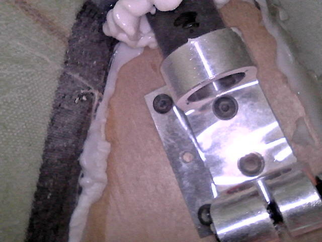
Bracket before removal.
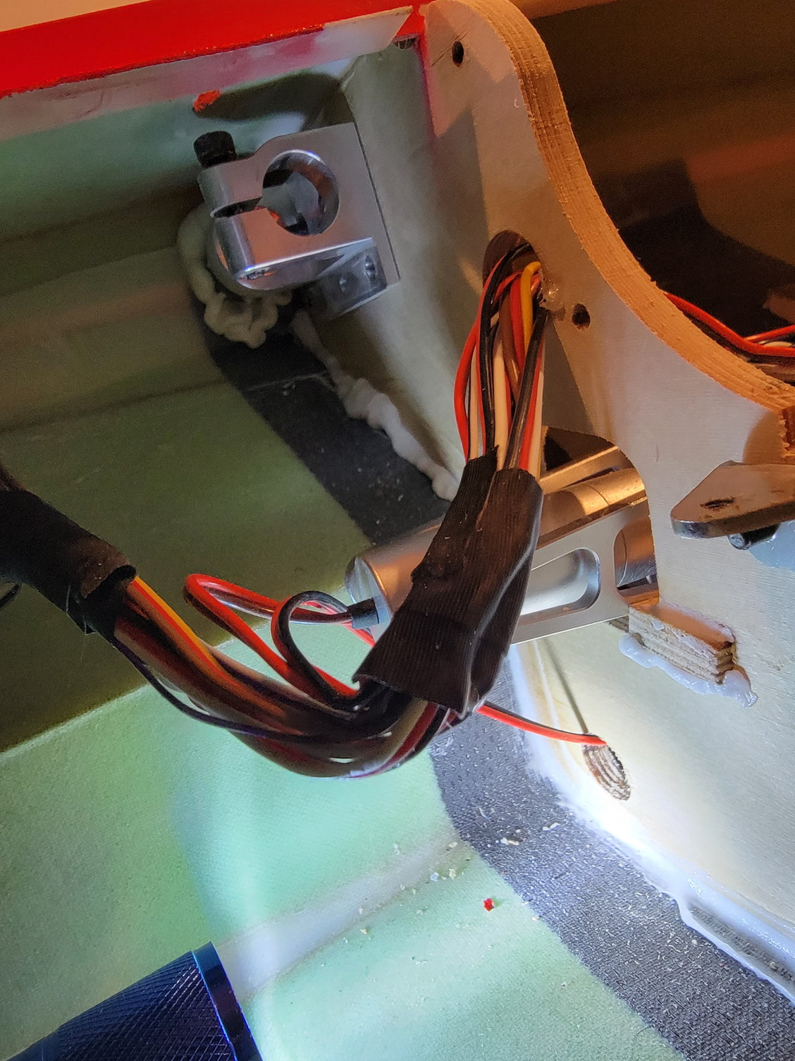
Wires were loosened a bit to make room to get my fat finger in there for removal
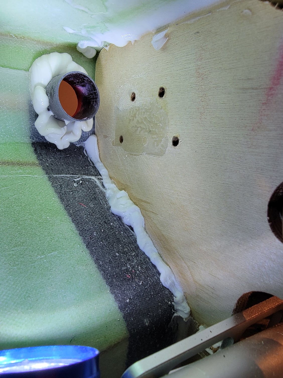
This is the former after the bracket was removed for inspection.

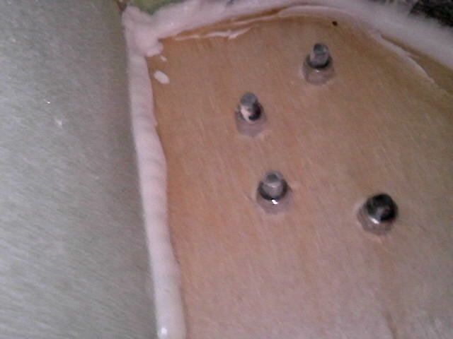
This is the rear of the bracket.
Thanks,
Tone
One thing I noticed and would advise everyone to check is the aluminum bracket that holds the wings. My left wing was a bit loose and required some attention. The right seemed okay. After looking into things, it became evident that the aluminum bracket that is mounted to the main former was a bit loose. This allowed the way some vertical movement and play. It is a bit hard to reach the screws; however, it is worth the effort to ensure these brackets are tight and secure as they are a significant component in securing the wing. The front anti-rotation pin was fine. I had to loosen the zip ties that secure the wire loom and remove the turbine rails to get to the bracket. From there, it was an effort in patience to remove the hardware, but it was doable. Once the bracket was removed, it appears that they also used glue to adhere the bracket to the former in addition to the allen screw and nuts; however, it does not appear that mine took very well. Therefore, my plan is to use a strong adhesive like hysol or E-6000 on the bracket before tightening and reinstalling. He also plans to install 3 mm washers before the nylon locknuts to increase the surface area. These efforts may not be necessary for everyone, but I would strongly caution everyone to check their brackets to make sure they are secure.
Bracket before removal.
Wires were loosened a bit to make room to get my fat finger in there for removal
This is the former after the bracket was removed for inspection.
This is the rear of the bracket.
Thanks,
Tone
12-29-2022, 06:04 PM
#19
Fuel tanks.
I decided to plumb the tanks. The kit comes with nice brass clunks, Festo "Y" fittings, clear Tygon fuel line, and pre-made fuel fittings that are pretty nice. The tanks' pressure tested okay, so I decided to get the tanks plumbed and ready to go. The kit comes with two fiberglass saddle tanks that hold 1800ml each. These flow into a third center tank that holds 800ml of fuel and feeds into the UAT. This makes for a total of 4400ml's of fuel and should ensure a nice long flight time.
I personally like to use filtered clunks. I like the Stens as it uses a filter composite material rather than fabric. I used these in the saddle tanks, and the brass clunk into the single main tank. I made my brass tubing with 4mm brass tubes with a small 5mm piece soldered to the end to help secure the tubing. For the clunk tubing, I like to use flexible Viton as it is chemical resistant and will work for some time. When you make your fuel line make sure that you keep it about a quarter inch from the nearer end of the tank to ensure that the clunk can freely move left to right. Everything was wire wrapped for security, and the tanks are ready to go.
On a side note, I did hysol a small aluminum bracket to the front of my main tank and a wood block to the fuse to help secure things. I will use a small bit of E-6000 at the back of the tank where it contacts the intakes, and it makes everything nice and tight. It is not strictly necessary, but as you may have guessed by now, I like ensuring things are secure.
Thanks for looking,
Tone
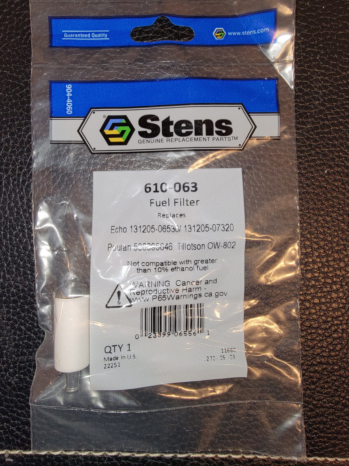

Stens filtered clunk.
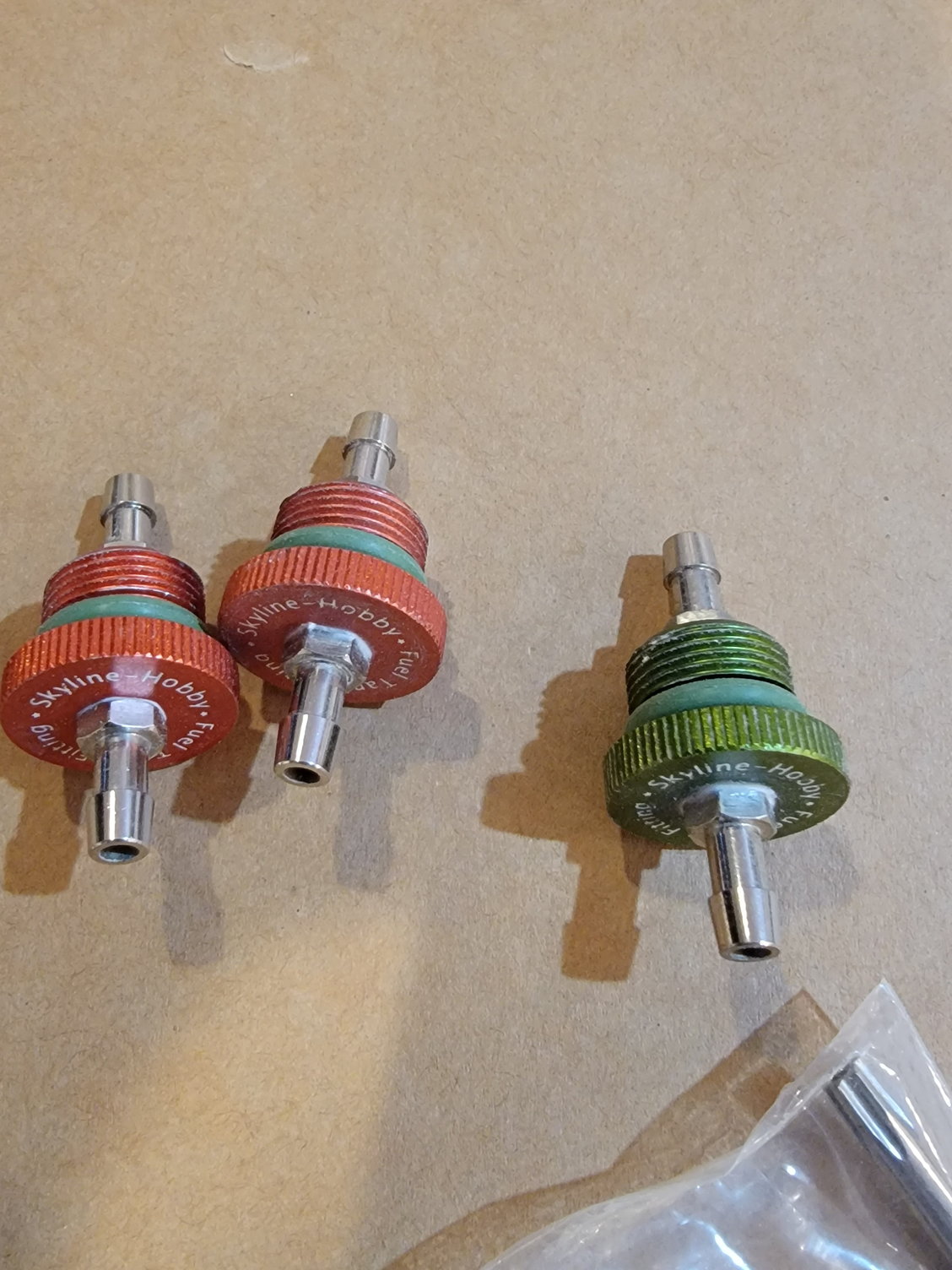
Fittings
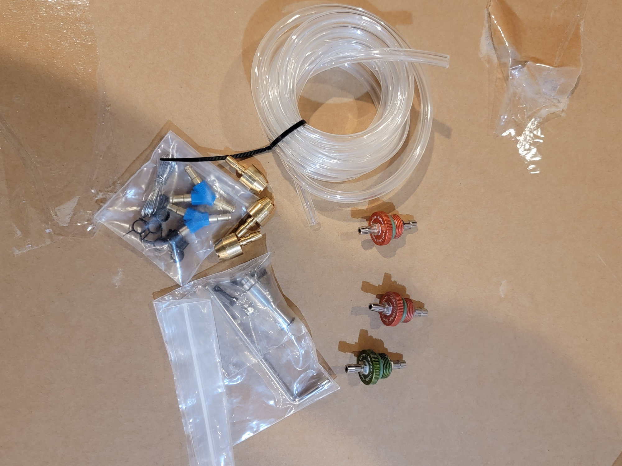
Fitting set that comes with the jet.
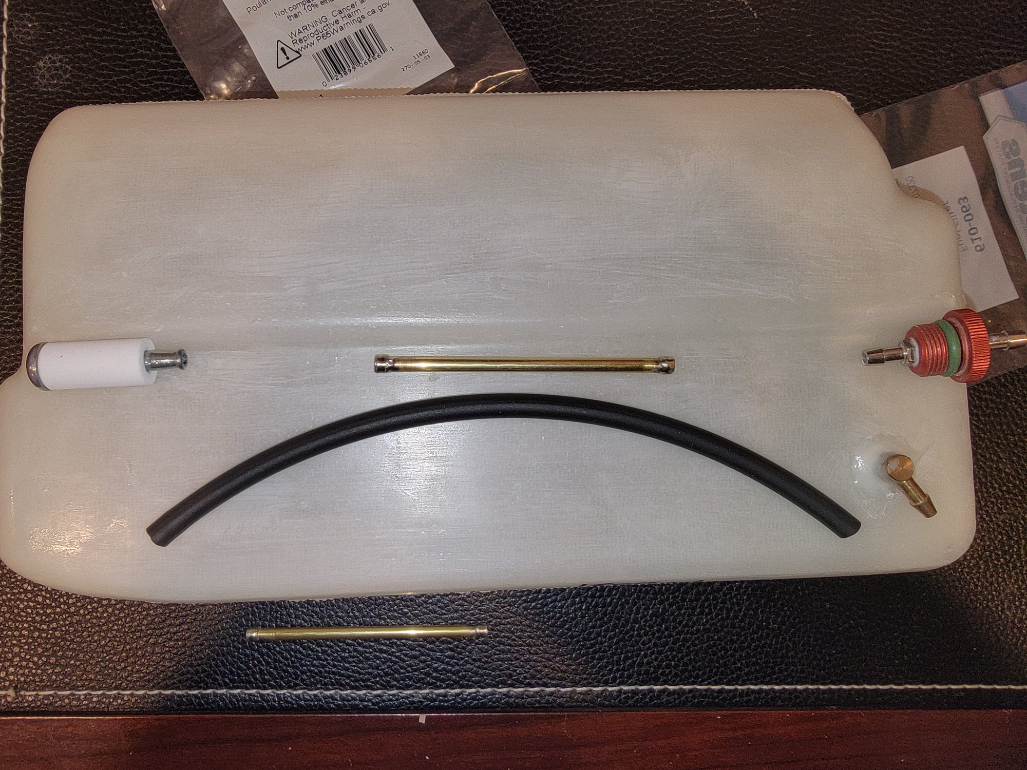
Filteres clunk, assembled brass tube and tank fitting. This is the left saddle tank.
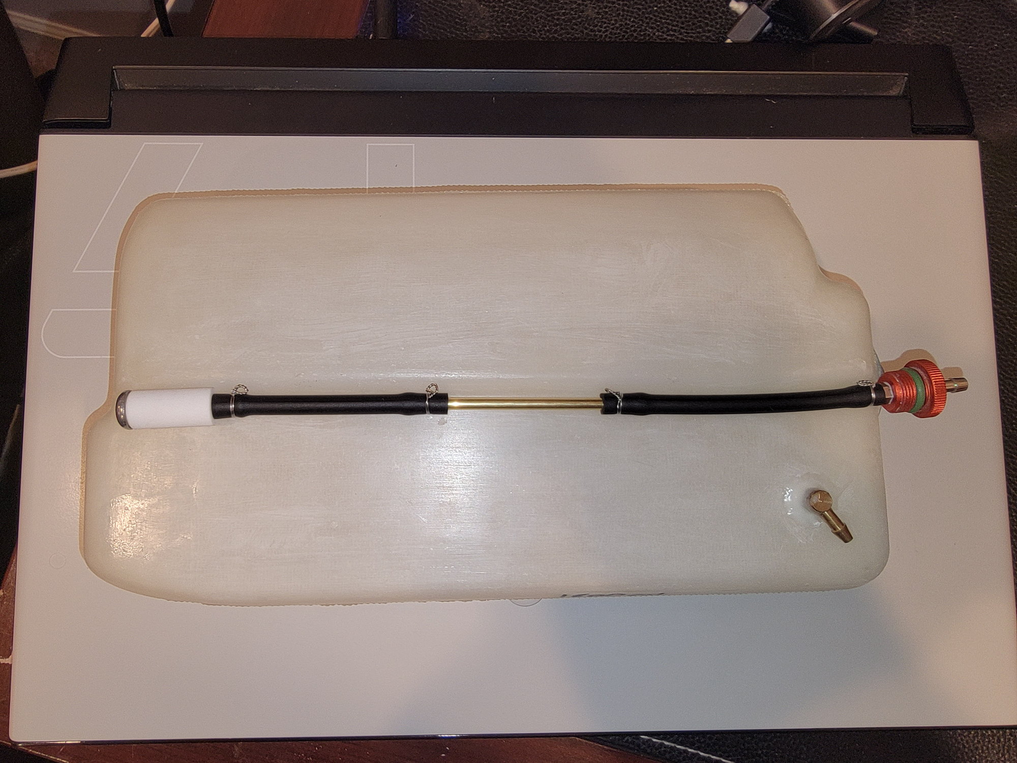
Completed clunk line. Its hard to tell from the pic but it is about 1/4" shorter than the tank to allow it to more freely.
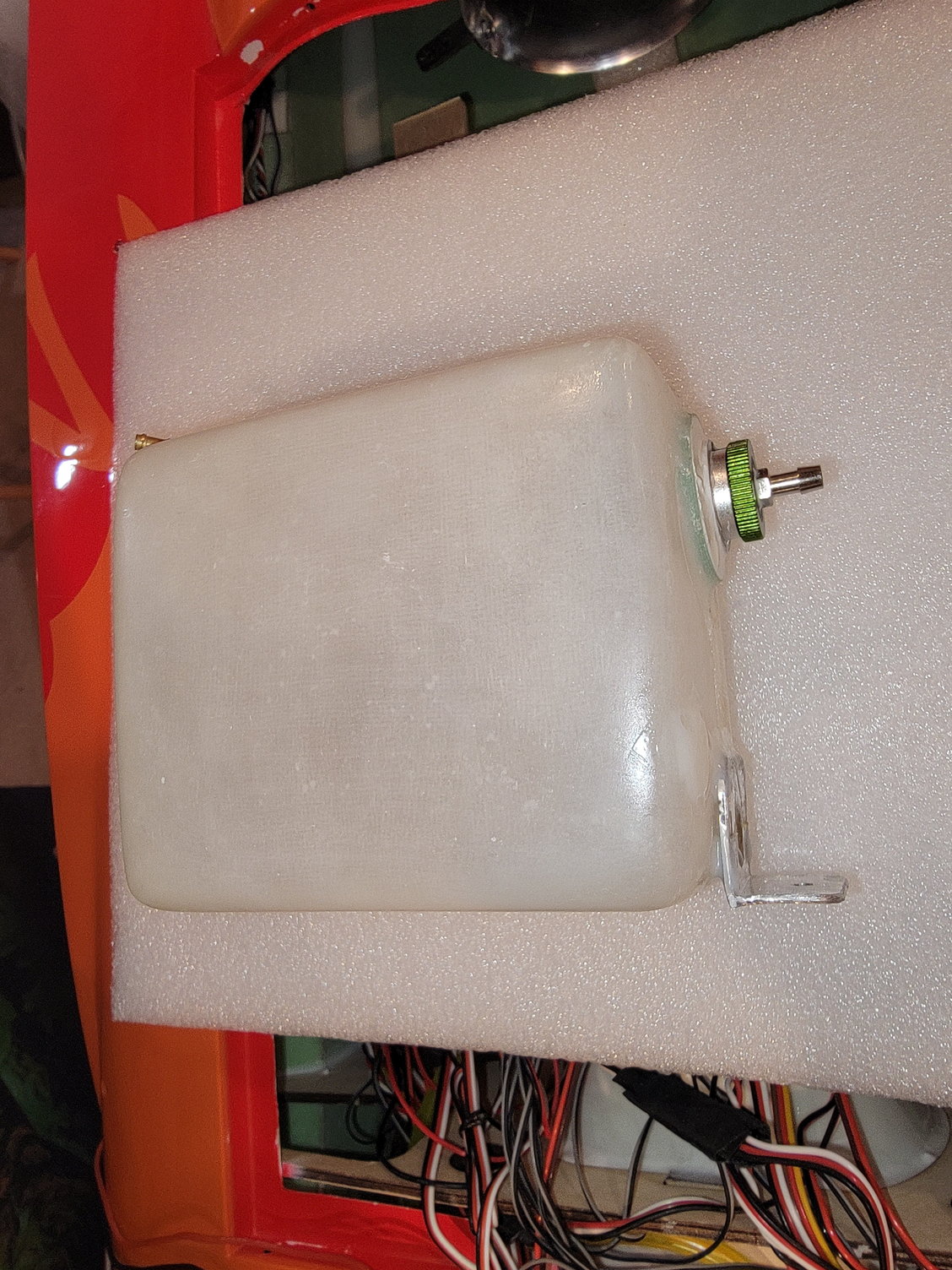
800ml main tank. Here you can see the aluminum brace I fabricated.
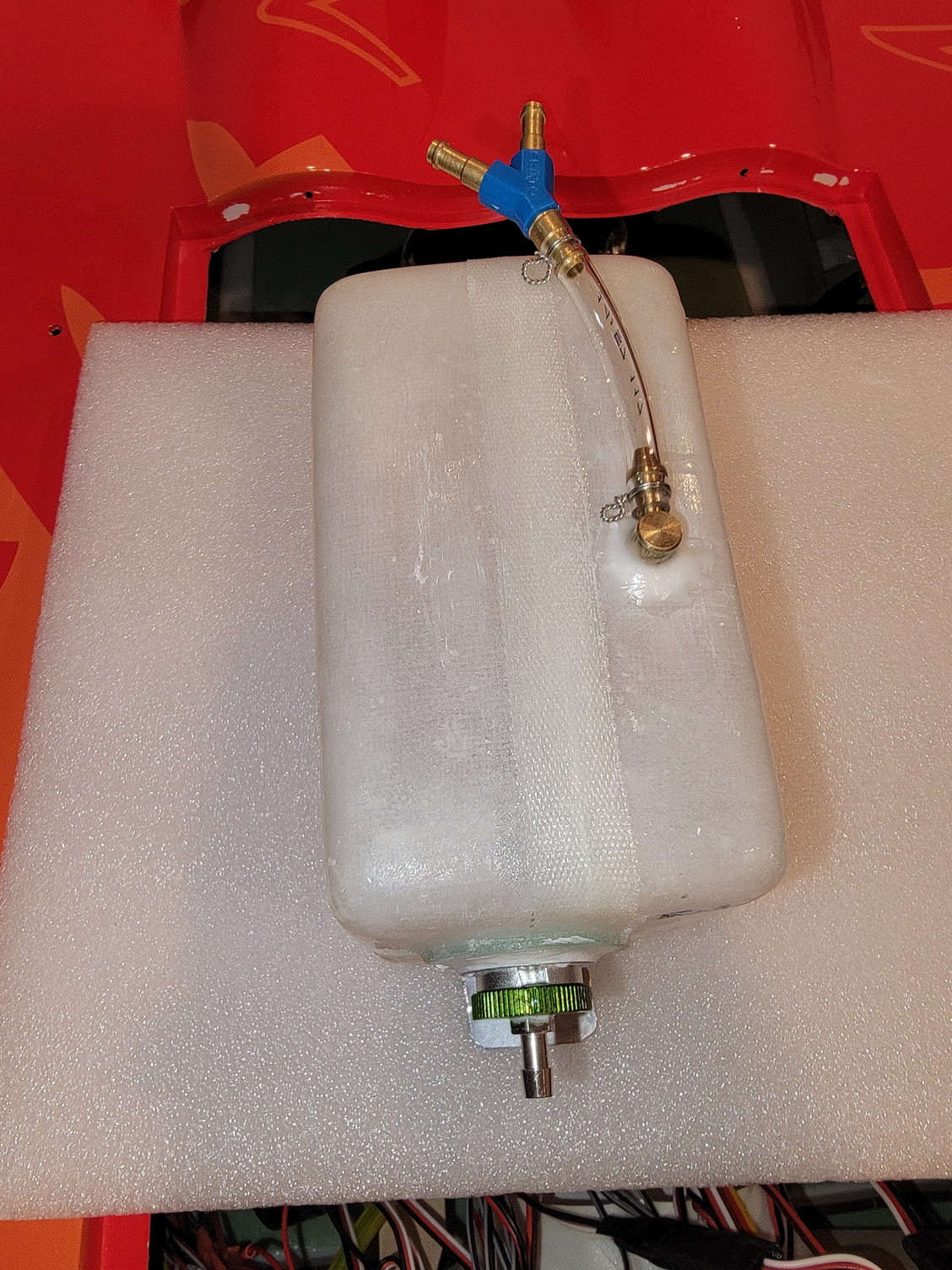
Assembled main tank with "Y" festo fitting that will go to the two saddle tanks.
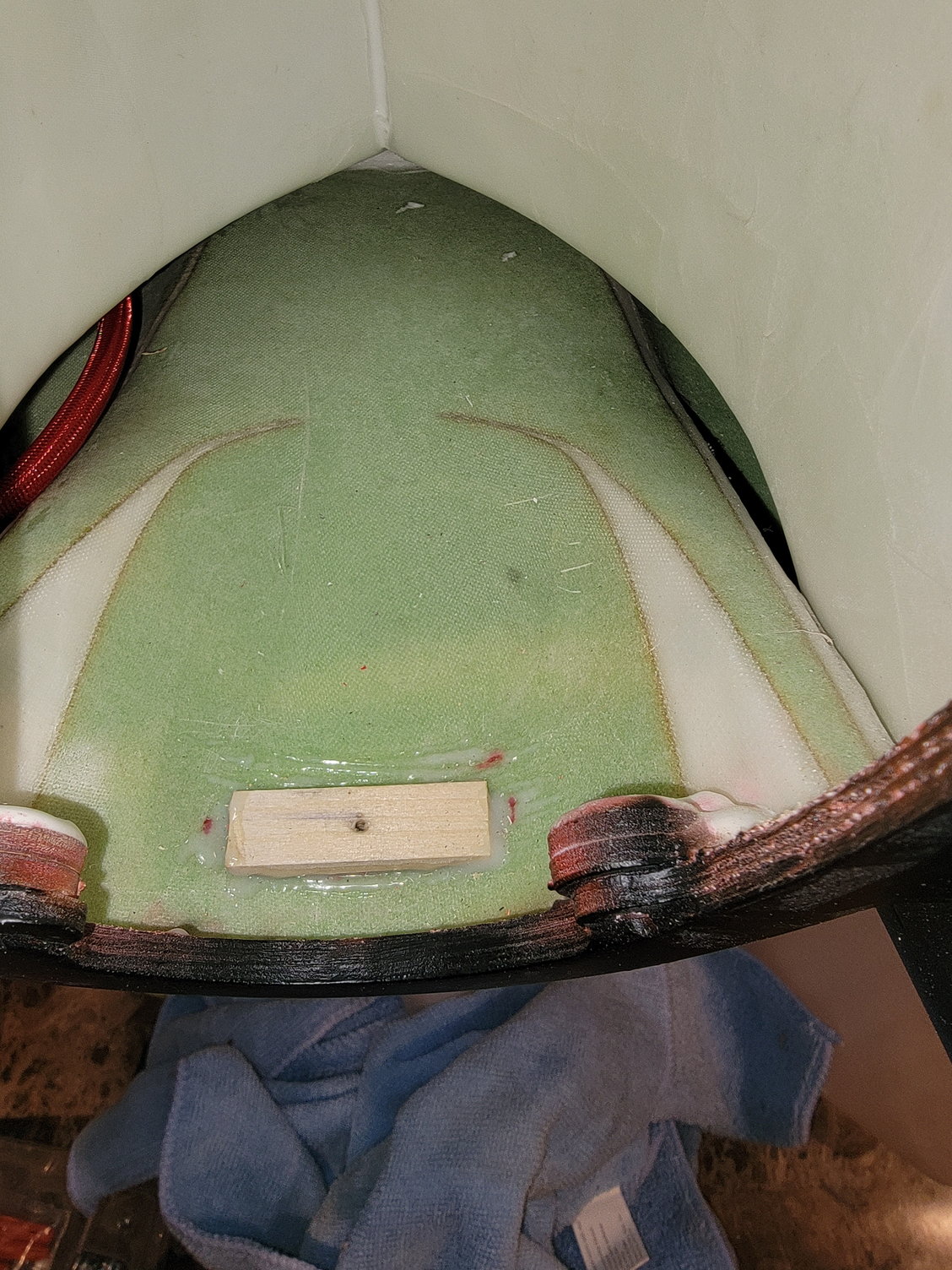
Wood block for the main tank.
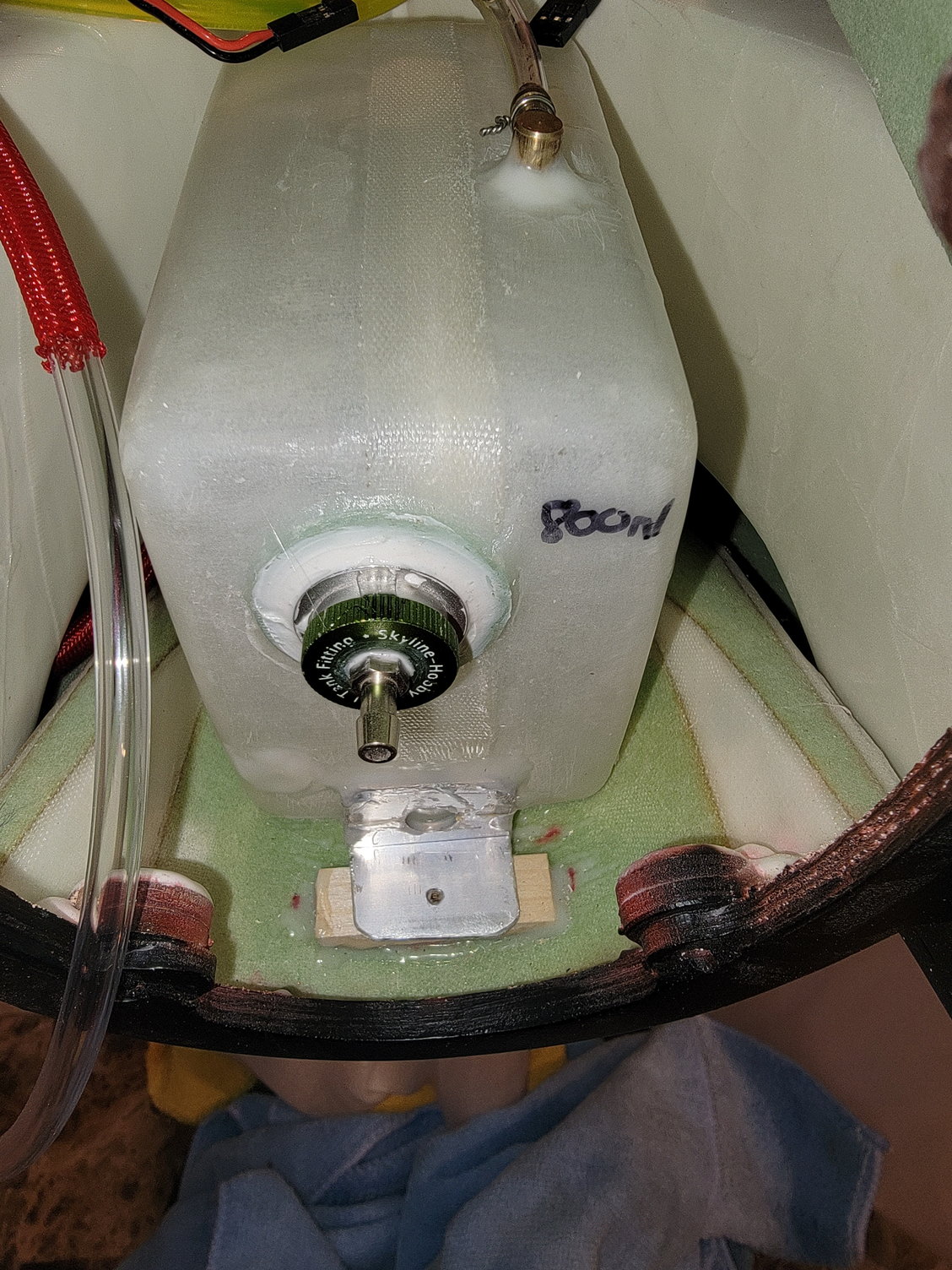
Main tank placement
I decided to plumb the tanks. The kit comes with nice brass clunks, Festo "Y" fittings, clear Tygon fuel line, and pre-made fuel fittings that are pretty nice. The tanks' pressure tested okay, so I decided to get the tanks plumbed and ready to go. The kit comes with two fiberglass saddle tanks that hold 1800ml each. These flow into a third center tank that holds 800ml of fuel and feeds into the UAT. This makes for a total of 4400ml's of fuel and should ensure a nice long flight time.
I personally like to use filtered clunks. I like the Stens as it uses a filter composite material rather than fabric. I used these in the saddle tanks, and the brass clunk into the single main tank. I made my brass tubing with 4mm brass tubes with a small 5mm piece soldered to the end to help secure the tubing. For the clunk tubing, I like to use flexible Viton as it is chemical resistant and will work for some time. When you make your fuel line make sure that you keep it about a quarter inch from the nearer end of the tank to ensure that the clunk can freely move left to right. Everything was wire wrapped for security, and the tanks are ready to go.
On a side note, I did hysol a small aluminum bracket to the front of my main tank and a wood block to the fuse to help secure things. I will use a small bit of E-6000 at the back of the tank where it contacts the intakes, and it makes everything nice and tight. It is not strictly necessary, but as you may have guessed by now, I like ensuring things are secure.
Thanks for looking,
Tone
Stens filtered clunk.
Fittings
Fitting set that comes with the jet.
Filteres clunk, assembled brass tube and tank fitting. This is the left saddle tank.
Completed clunk line. Its hard to tell from the pic but it is about 1/4" shorter than the tank to allow it to more freely.
800ml main tank. Here you can see the aluminum brace I fabricated.
Assembled main tank with "Y" festo fitting that will go to the two saddle tanks.
Wood block for the main tank.
Main tank placement
12-29-2022, 06:20 PM
#20
UAT
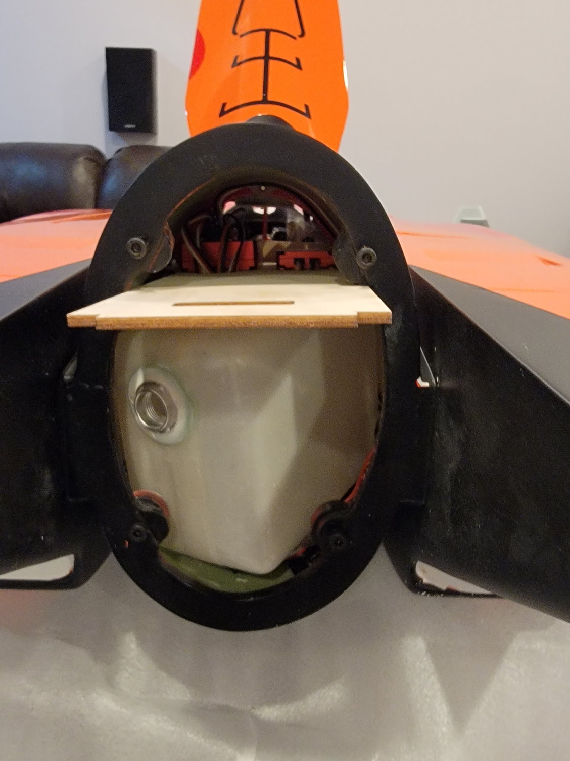
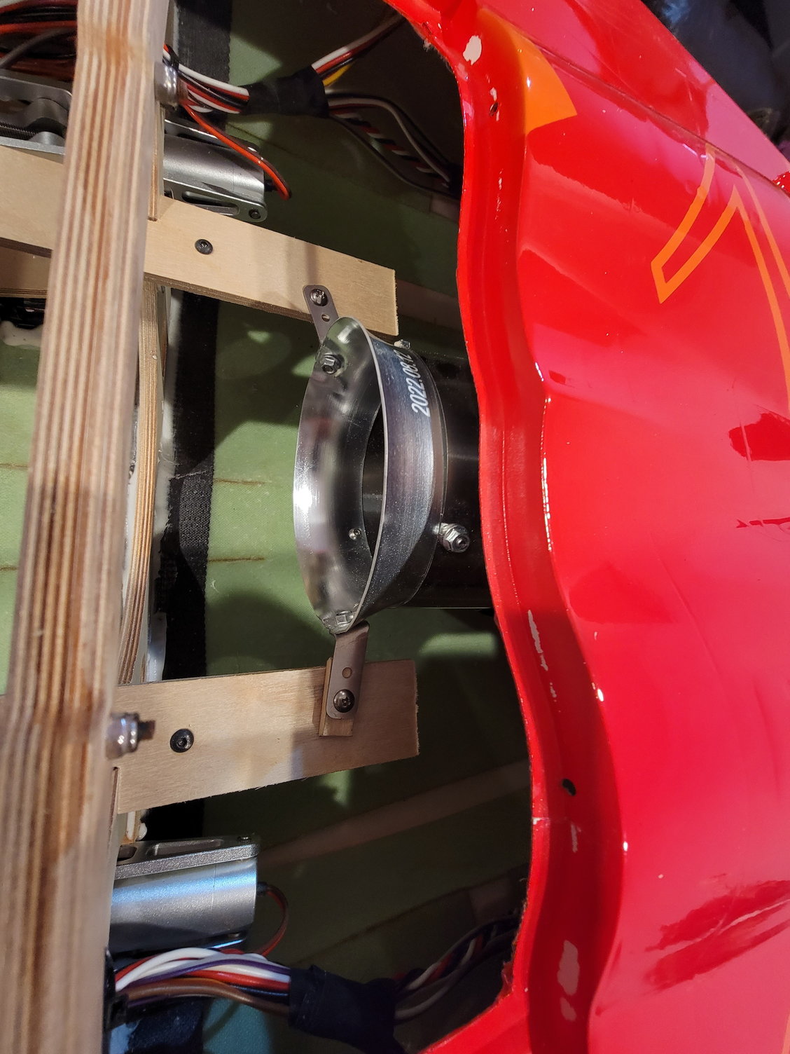
As I previously said, even though the jet is plug-and-play, I tend to check everything. One thing I noticed while setting up my fuel tank was that while the UAT was plumbed, there were no wire wraps in place, which for me, is a must. I originally planned to use an Interairco or Digitech uat anyway, so I had planned to remove the UAT anyway. The stock UAT is 150cc and is located behind the intake on the right-hand side. It is the kind with the plastic bottle and fittings, similar to the Kingtech version. The jet also uses the clear Tygon-type fuel lines. Getting it out was a bit tight, but I was able to get in there with some scissors, cut the two zip ties, and removed the stock UAT with some finagling. When I disassembled it, I noticed that the strainer was made of plastic and did not have a filter sock. This is still an effective and there is nothing wrong with this set up, but I personally prefer a filter sock for fine particles. Instead of adding a sock, and since I already had a 160cc Digitech waiting g for a project, I attempted to replace the stock UAT with the Digitech. However, the opening was much too tight for the Digitech, so I had to think of another option. My options were that I could just use the stock UAT as is, I could add filter material or a filter sock to the stock UAT and use it as is, or go another route. Since I also had 150cc Kingetech UAT sitting on my parts wall as a spare, I decided to go that route as it already had a filter sock in place, and it would be an easy swap out.
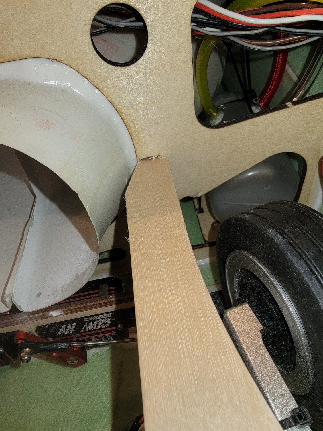
I like the harder 6mm polyurethane fuel tubing, so I used that on my UAT and fuel tanks. I did make a small notch in the former to make it a bit easier to get the new UAT and the stiffer fuel lines in place. I did add a few inches of sleeving to any possible friction areas' and when I was happy with the placement, I put a little E-6000 adhesive in a few places to keep it from rotating.
Thanks for looking,
Tone
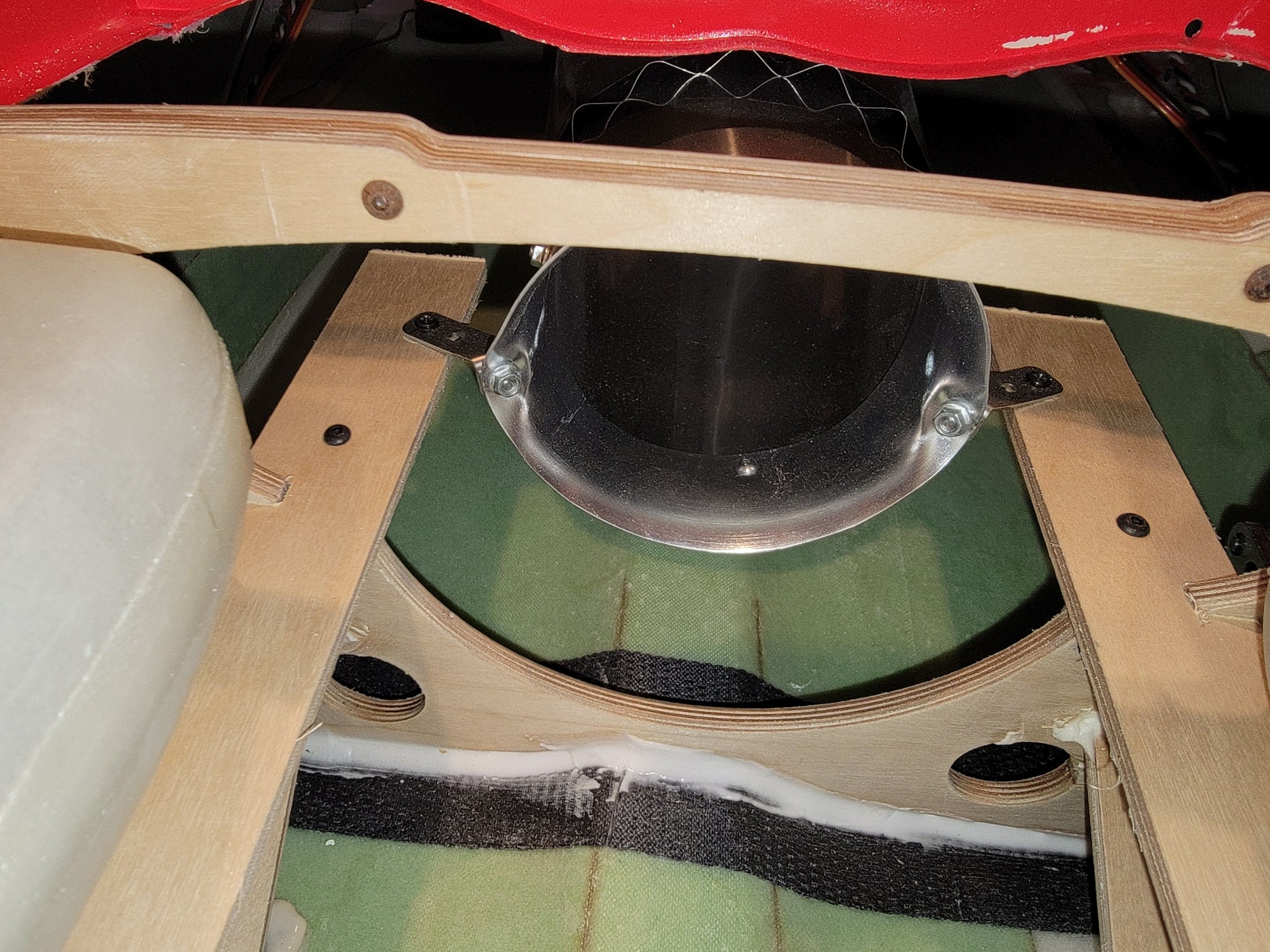
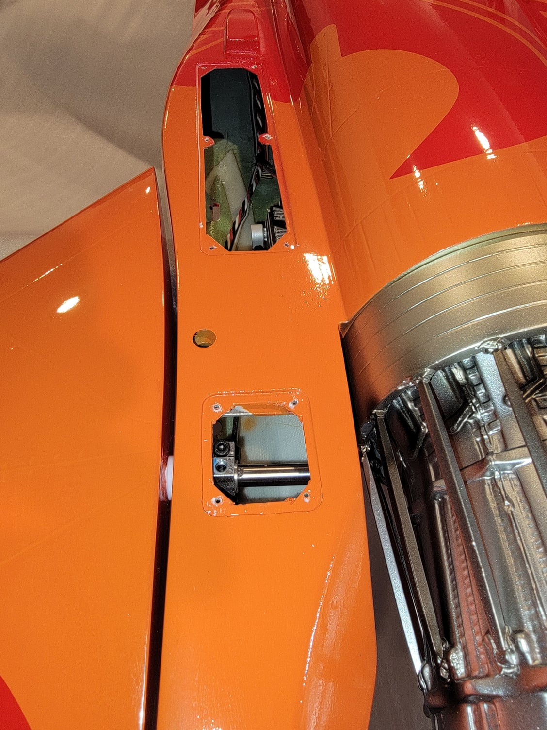
Its a bit hard to see, but here you can the placement of the UAT behind the intake.
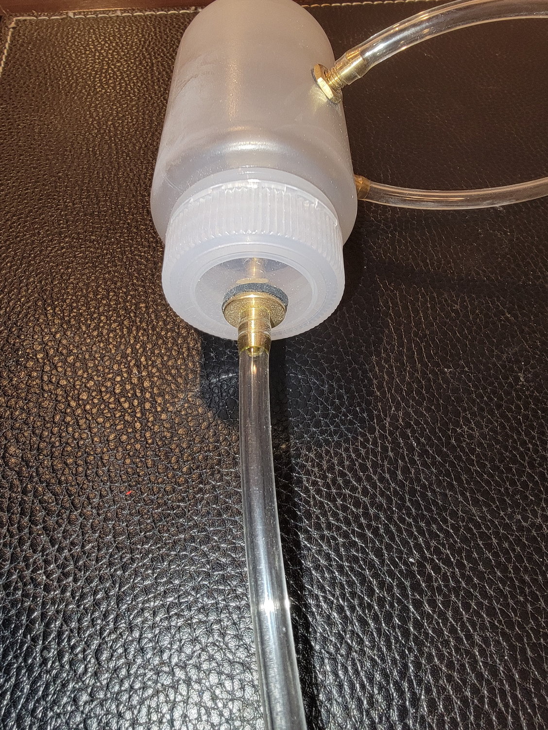
Stock UAT
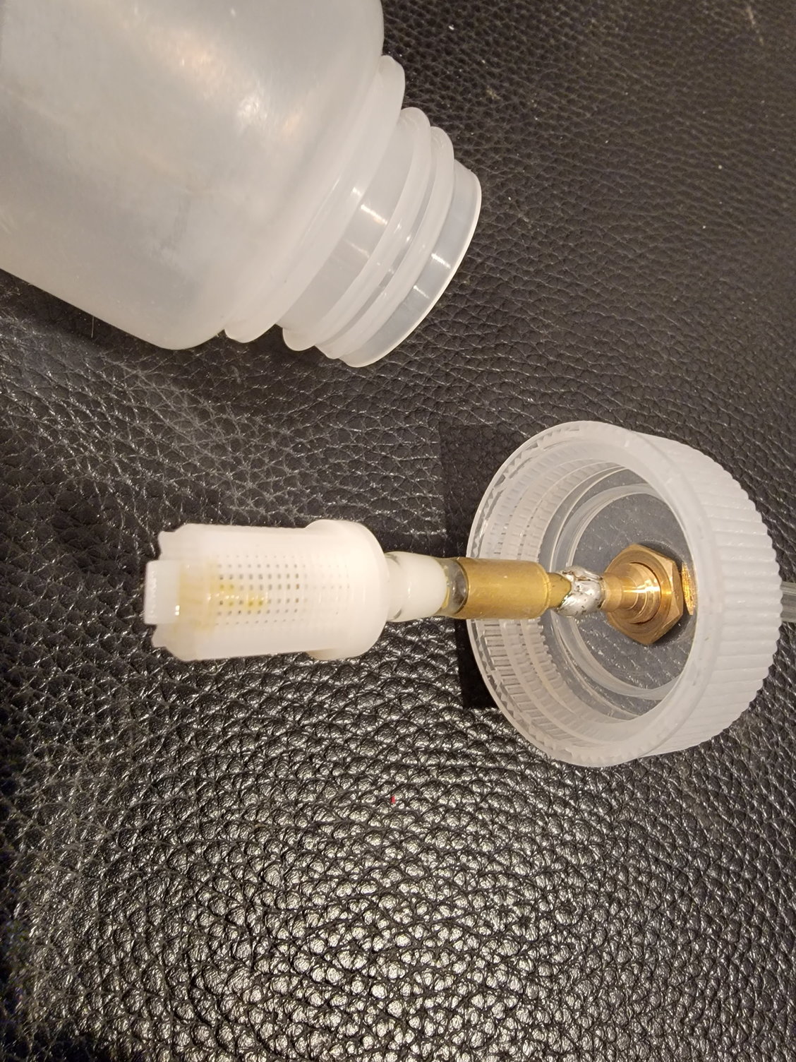
Here is the stock UAT filter. It works just fine. I just like the filtered socks for fine particles.
Here is the spot behind the intake after the UAT was removed.

The sleeve material protecting the fuel lines.
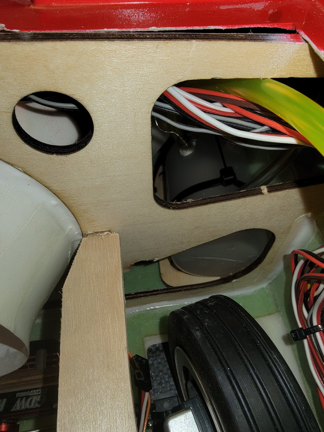
If you look to the right of the turbine rail and above the tire you can see the small notch in the former I added to help insert the new UAT.
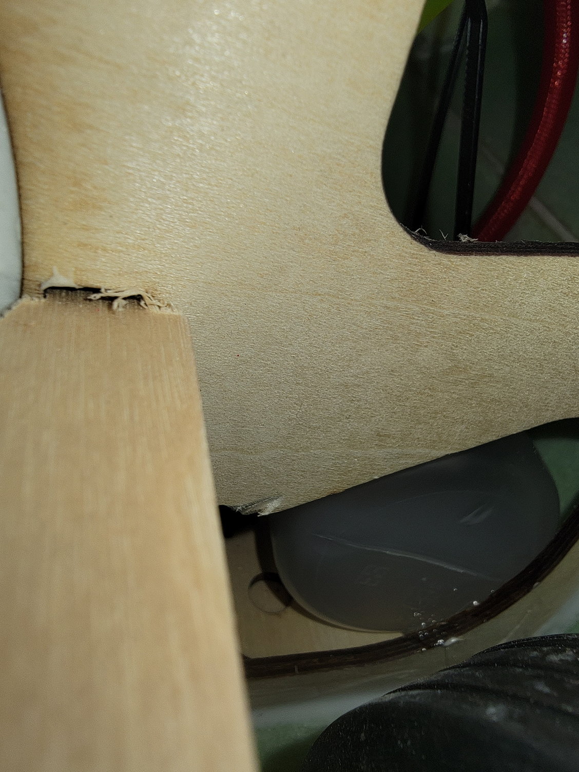
Here you can see a small amount of adhesive on the bottom of the plastic bottle and the former to keep it from rotating.
As I previously said, even though the jet is plug-and-play, I tend to check everything. One thing I noticed while setting up my fuel tank was that while the UAT was plumbed, there were no wire wraps in place, which for me, is a must. I originally planned to use an Interairco or Digitech uat anyway, so I had planned to remove the UAT anyway. The stock UAT is 150cc and is located behind the intake on the right-hand side. It is the kind with the plastic bottle and fittings, similar to the Kingtech version. The jet also uses the clear Tygon-type fuel lines. Getting it out was a bit tight, but I was able to get in there with some scissors, cut the two zip ties, and removed the stock UAT with some finagling. When I disassembled it, I noticed that the strainer was made of plastic and did not have a filter sock. This is still an effective and there is nothing wrong with this set up, but I personally prefer a filter sock for fine particles. Instead of adding a sock, and since I already had a 160cc Digitech waiting g for a project, I attempted to replace the stock UAT with the Digitech. However, the opening was much too tight for the Digitech, so I had to think of another option. My options were that I could just use the stock UAT as is, I could add filter material or a filter sock to the stock UAT and use it as is, or go another route. Since I also had 150cc Kingetech UAT sitting on my parts wall as a spare, I decided to go that route as it already had a filter sock in place, and it would be an easy swap out.
I like the harder 6mm polyurethane fuel tubing, so I used that on my UAT and fuel tanks. I did make a small notch in the former to make it a bit easier to get the new UAT and the stiffer fuel lines in place. I did add a few inches of sleeving to any possible friction areas' and when I was happy with the placement, I put a little E-6000 adhesive in a few places to keep it from rotating.
Thanks for looking,
Tone
Its a bit hard to see, but here you can the placement of the UAT behind the intake.
Stock UAT
Here is the stock UAT filter. It works just fine. I just like the filtered socks for fine particles.
Here is the spot behind the intake after the UAT was removed.
The sleeve material protecting the fuel lines.
If you look to the right of the turbine rail and above the tire you can see the small notch in the former I added to help insert the new UAT.
Here you can see a small amount of adhesive on the bottom of the plastic bottle and the former to keep it from rotating.
12-30-2022, 05:56 AM
#21
My tanks are plumbed in series. The forward tank feeds first to keep a rear cg for landing. The lateral weight imbalance is not noticeable as the weight is so close to the cg. I used a BVM UAT and am surprised I am having problems. Most likely I have a loose connection on the pickup fuel line. I may move UAT to make it easier to service I'd I can find a suitable location.
12-30-2022, 05:46 PM
#22
My tanks are plumbed in series. The forward tank feeds first to keep a rear cg for landing. The lateral weight imbalance is not noticeable as the weight is so close to the cg. I used a BVM UAT and am surprised I am having problems. Most likely I have a loose connection on the pickup fuel line. I may move UAT to make it easier to service I'd I can find a suitable location.
Thanks,
Tone
01-07-2023, 03:12 PM
#25
Well it flew. t/o roll about 300' (no flap) Kinda jumped off the ground but very controllable. cg 7.5 behind le of wing and only required 1-2 clicks of elev trim. Required a bit of aileron trim but didnt investigate why. Was a little nose heavy at first but was expected. Flew about 6 min and landed with one saddle almost full. I landed a little long and hot, and ran off end of runway, Bent main struts and broke one mount, both easily fixed. Will order parts, repair and continue test flight program. Overall it flys well and looks good in the air. Im happy.