


1/4.5 T-38C Talon scratch build
 12-25-2019, 05:05 PM
#51

My Feedback: (20)

Don't want to hijack Thomas's thread here but short story is...yes. The outer 3' of the wing tips are honeycomb aluminum sandwiched between top and bottom skins. Skins could delaminate and fail causing the tip to break off. Tip fails were a known problem along with other wing issues in the late 70s and the jets were limited to 5G. In this case we had a tip fail at 5G and it departed the jet doing damage to the fuse side as it folded up and rolled over inboard. This caused the jet to pitch up and exceed 8G which broke the other tip off because of same the failure. This all happened in about 1 second. After the big boom and lurch, and after getting my heart started again, I was shocked to see both wing tips gone. Structural damage checks showed we were good to 180kts which was a normal no flap landing speed, so landing was mostly uneventful except for the "pucker factor."
I have about 1200 hrs in T-38s and always wanted to model one. If I ever do, it will have the 46366 tail number and white scheme because of this flight!
Gary
 12-25-2019, 06:14 PM
#52
Junior Member
Join Date: Dec 2019
Posts: 17
Likes: 0
Received 0 Likes
on
0 Posts
my dad ran NDI non-destructive investigation on t-38 wings in the 70�s. Our house was in the landing pattern an t-38s flew over my house every few minutes... prettiest plane.
vance afb and USAF is retiring t-38s and replacing the with the t-7a redhawks.. thats a pretty plane too...
j
vance afb and USAF is retiring t-38s and replacing the with the t-7a redhawks.. thats a pretty plane too...
j

 12-26-2019, 06:27 PM
#55
My Feedback: (20)
I think the RC would fly better with both wingtips! Don't need any more pucker factor landing the RC version. I get enough of that each landing now!
By the way I grew up in your neighborhood in Baytown, TX. The wingtip even occurred south of Wichita Falls, TX where I was based at Sheppard AFB. A local rancher returned the both wingtips back to the base about a month later. The Air Force awarded me a ball point pen for saving the jet. As they say... the reward for a job well done is no punishment!
Gary


 01-17-2020, 11:13 AM
#62
Thanks guys. Its getting there slowly.. still alot of sanding left to do, but im pretty confident these will be the nicest plugs and molds i have done. It has been decided to throw some extra $$$$ into more production oriented materials so the molds will last longer and produce nice parts. Mostly so if approached by a third party on purchasing the tooling and design data, that buyer will have better tooling to get started with.
01-22-2020, 08:27 PM
#63

Thomas,
That wing is looking great - glad the laser engraving process is working out. I should have patented the process, but cut you into the profits as you suggested it in he first place!!!
Makes me wish I'd got a bigger laser so that I could put bigger panels into it.
Paul
That wing is looking great - glad the laser engraving process is working out. I should have patented the process, but cut you into the profits as you suggested it in he first place!!!
Makes me wish I'd got a bigger laser so that I could put bigger panels into it.
Paul
01-23-2020, 08:20 AM
#64
Thomas,
That wing is looking great - glad the laser engraving process is working out. I should have patented the process, but cut you into the profits as you suggested it in he first place!!!
Makes me wish I'd got a bigger laser so that I could put bigger panels into it.
Paul
That wing is looking great - glad the laser engraving process is working out. I should have patented the process, but cut you into the profits as you suggested it in he first place!!!
Makes me wish I'd got a bigger laser so that I could put bigger panels into it.
Paul
LoL. Im glad you took the charge to see if it would work! Knowing it would work made the decision of getting a laser easier and is one reason i decided to get the biggest one i could afford and fit. The table is massive!
 01-25-2020, 01:38 PM
#69
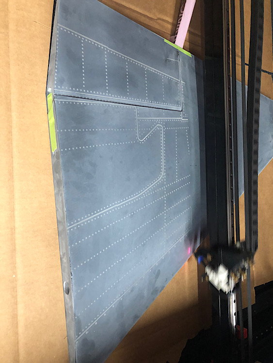
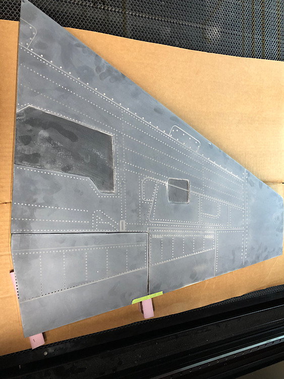
Ive been in Nyc for the past week and still have a week to go, so ive been doing cad work.
To make my life easier and produce some nicer parting planes, i have been designed and drawing them in CAD. There is a combination of 3D printed and laser cut ones. In the following photos, the green pieces will be 3D printed. The striations will just be tapes over to reduce the labor involved and provide a nice smooth surface. The pink pieces will be laser cut from the smooth white tempered hardboard:
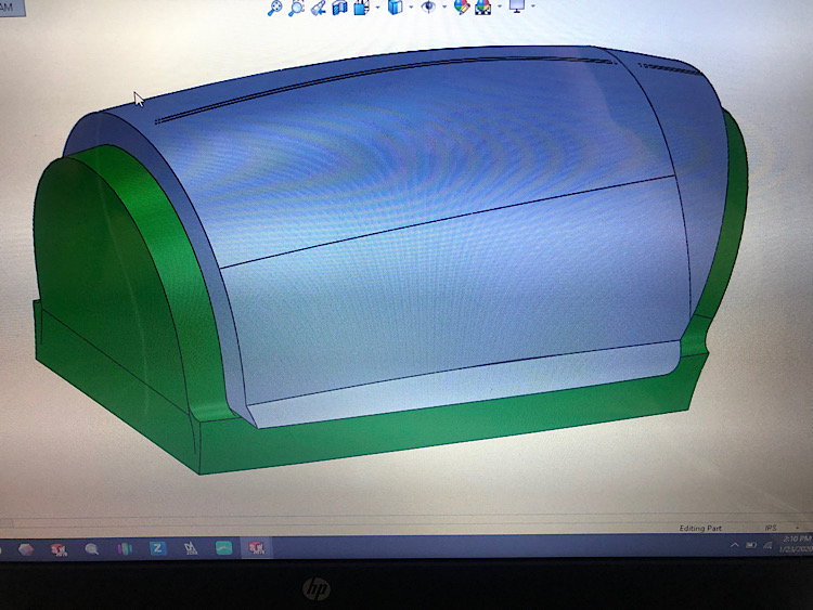
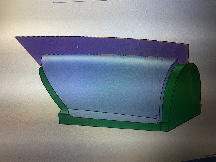
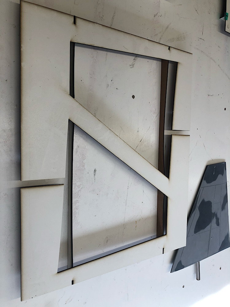
I have also been working on the remainder of the parting planes for the airframe. All of the tail section and wings are completed and ready to be cut (if they arent cut already). The Flaps are a unique challenge due to the Quarter round of the Leading edges. You cant just cut these in half or else you end up with a negative draft and that makes getting the parts out difficult at best or even impossible. Not wanting to do a 3 piece mold for the flap, i elected to go with what is in the following photo. It uses some 1� foam insulation as a �cradleL and then 2 pieces of laser cut hardboard for the parting planes. The slot you see at one end is for the aluminum Hex shaft that doubles as the inboard flap hinge and the control arm attachment.
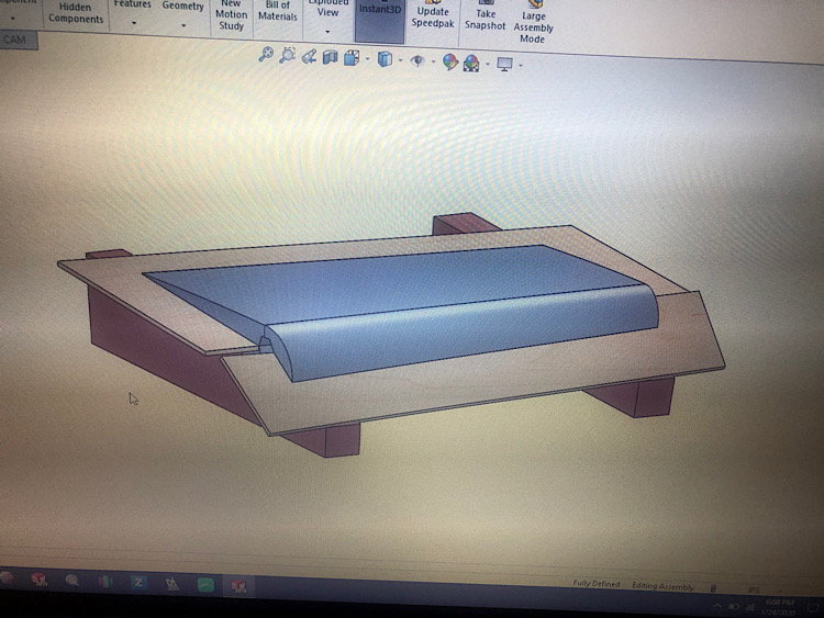
I have also been working on the files so the Airex core material can be laser cut and the perforations added.
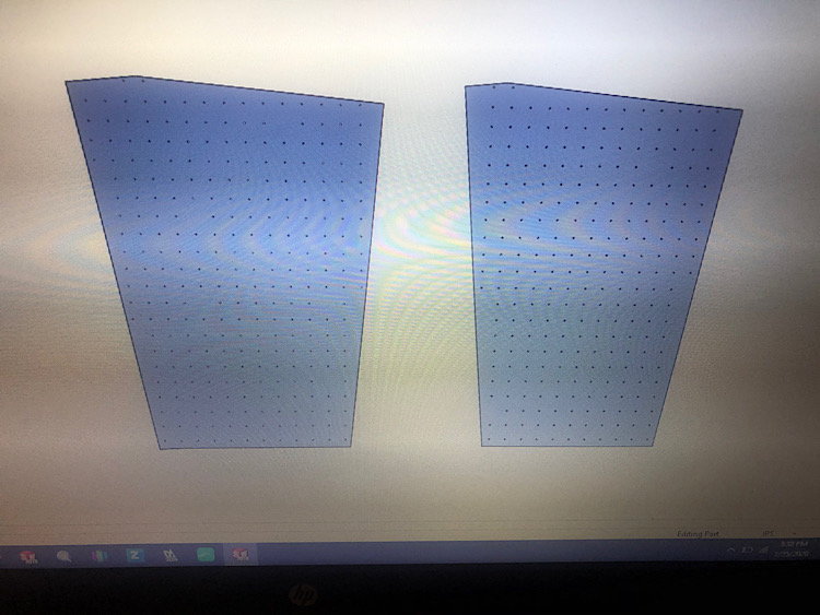
The Landing gear Cad work is also starting to come together. The main gear is 90% done with just a few tweaks needed to get it to the correct length. The nose gear is also slowly coming along as well.
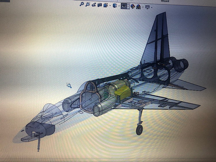
The Project folder containing Just the CAD data for this project is currently sitting at 8 GIGS. Its slowly beginning to catchup to the F14 folder which is just over 20Gigs. LoL
To make my life easier and produce some nicer parting planes, i have been designed and drawing them in CAD. There is a combination of 3D printed and laser cut ones. In the following photos, the green pieces will be 3D printed. The striations will just be tapes over to reduce the labor involved and provide a nice smooth surface. The pink pieces will be laser cut from the smooth white tempered hardboard:
I have also been working on the remainder of the parting planes for the airframe. All of the tail section and wings are completed and ready to be cut (if they arent cut already). The Flaps are a unique challenge due to the Quarter round of the Leading edges. You cant just cut these in half or else you end up with a negative draft and that makes getting the parts out difficult at best or even impossible. Not wanting to do a 3 piece mold for the flap, i elected to go with what is in the following photo. It uses some 1� foam insulation as a �cradleL and then 2 pieces of laser cut hardboard for the parting planes. The slot you see at one end is for the aluminum Hex shaft that doubles as the inboard flap hinge and the control arm attachment.
I have also been working on the files so the Airex core material can be laser cut and the perforations added.
The Landing gear Cad work is also starting to come together. The main gear is 90% done with just a few tweaks needed to get it to the correct length. The nose gear is also slowly coming along as well.
The Project folder containing Just the CAD data for this project is currently sitting at 8 GIGS. Its slowly beginning to catchup to the F14 folder which is just over 20Gigs. LoL
01-25-2020, 03:27 PM
#70
Thomas,
The CAD work looks great.
It's humbling to see some of the crazy self-taught ideas that I thought up and tried on my Buccaneer project being adopted by folks that are way more experienced in this area of model building than I. I was just making sh*t up as I went along, but for the most part it seems to work. The laser surface detailing and the laser cut and perforated Airex foam skins too.
Interesting to see some of the improvements that you are trying, such as laminated hardboard vs. my foam poster board parting planes. I have modified my approach slightly by covering the foam poster board with the self-adhesive vinyl-cutter material before I laser cut the parting planes in order to get an easy release. The surface coat doesn't stick to the vinyl surface.
Keep up the good work.
Paul
01-25-2020, 03:51 PM
#71
Thomas,
The CAD work looks great.
It's humbling to see some of the crazy self-taught ideas that I thought up and tried on my Buccaneer project being adopted by folks that are way more experienced in this area of model building than I. I was just making sh*t up as I went along, but for the most part it seems to work. The laser surface detailing and the laser cut and perforated Airex foam skins too.
Interesting to see some of the improvements that you are trying, such as laminated hardboard vs. my foam poster board parting planes. I have modified my approach slightly by covering the foam poster board with the self-adhesive vinyl-cutter material before I laser cut the parting planes in order to get an easy release. The surface coat doesn't stick to the vinyl surface.
Keep up the good work.
Paul
The CAD work looks great.
It's humbling to see some of the crazy self-taught ideas that I thought up and tried on my Buccaneer project being adopted by folks that are way more experienced in this area of model building than I. I was just making sh*t up as I went along, but for the most part it seems to work. The laser surface detailing and the laser cut and perforated Airex foam skins too.
Interesting to see some of the improvements that you are trying, such as laminated hardboard vs. my foam poster board parting planes. I have modified my approach slightly by covering the foam poster board with the self-adhesive vinyl-cutter material before I laser cut the parting planes in order to get an easy release. The surface coat doesn't stick to the vinyl surface.
Keep up the good work.
Paul
Paul,
Sometimes we cant see the forest from the tree�s. Your idea�s with the laser cut airex and its perforations is a great idea. I had been using a monokote �wood-pecker� to do the perforations. It was effective, but not very consistent.
I have been using the white tempered hardboards for a good while for parting planes. Its cheap and easy to cut, even by hand with just a jig saw and releases very well. I had been using MDF shelf board, but that was entirely to thick and heavy... and Expensive!
i need to figure out how to pull off your gear door inner surface molds, that idea is super cool and one i would like to do!
03-24-2020, 04:41 PM
#73
Finally got around to doing some T38 stuff.
I got the horizontal stab parting planes laser cut, then waxed the H. Stabs and rudder, got them put into position in the parting planes, filled the gaps, waxed everything 3 more times and then sprayed the Pva.

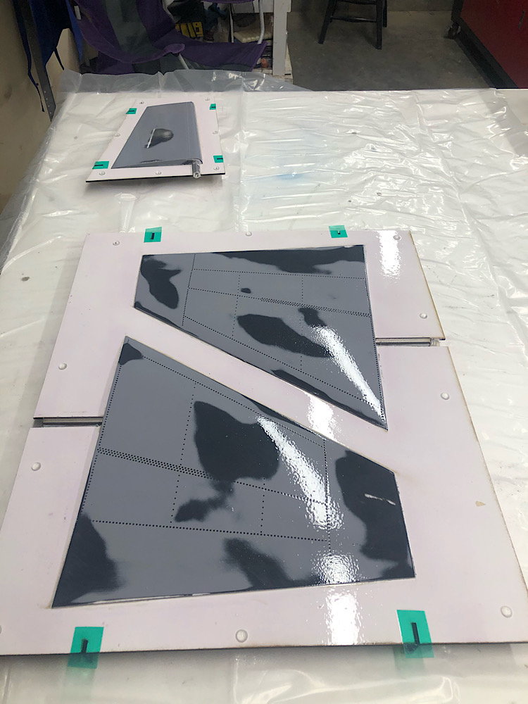
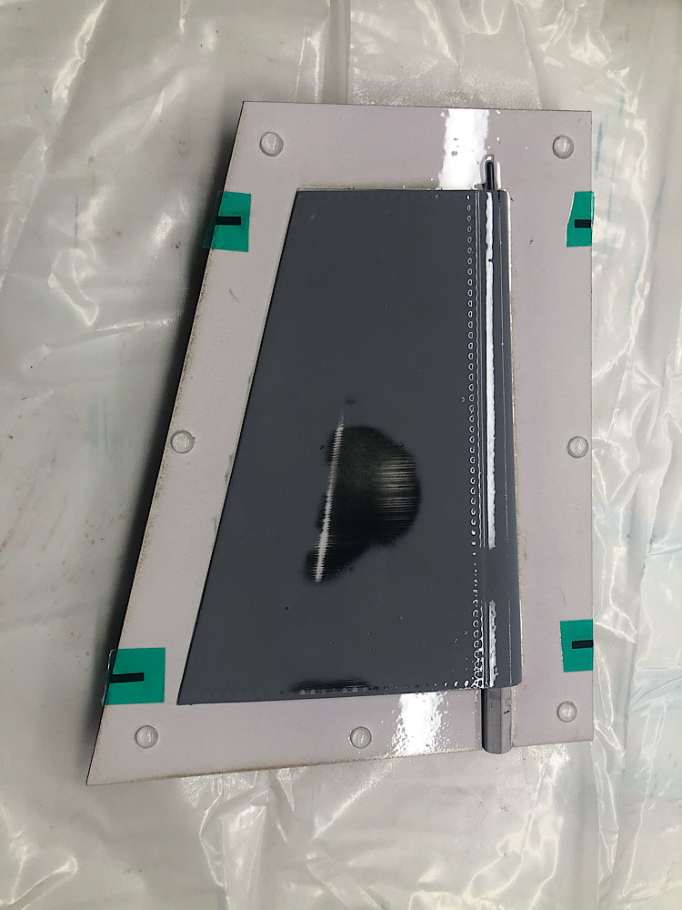
I got the horizontal stab parting planes laser cut, then waxed the H. Stabs and rudder, got them put into position in the parting planes, filled the gaps, waxed everything 3 more times and then sprayed the Pva.